











Kings of War A Veteran Wargamer's Newbie Guide



Ratkin: Building A Death Engine
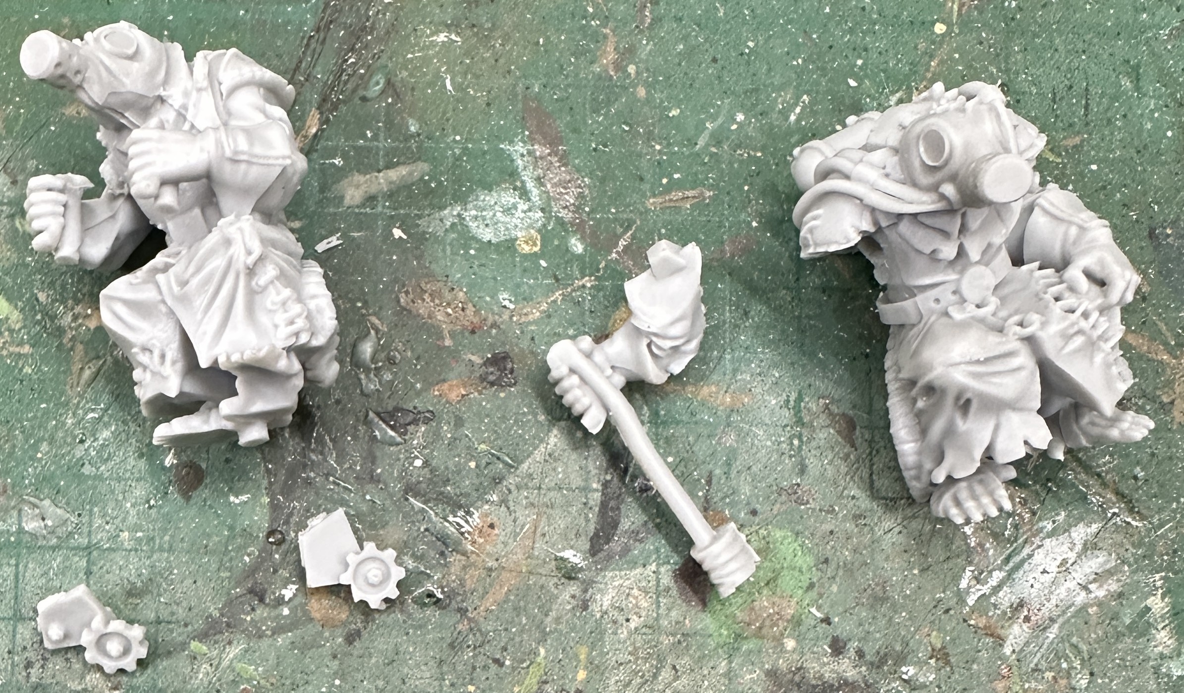
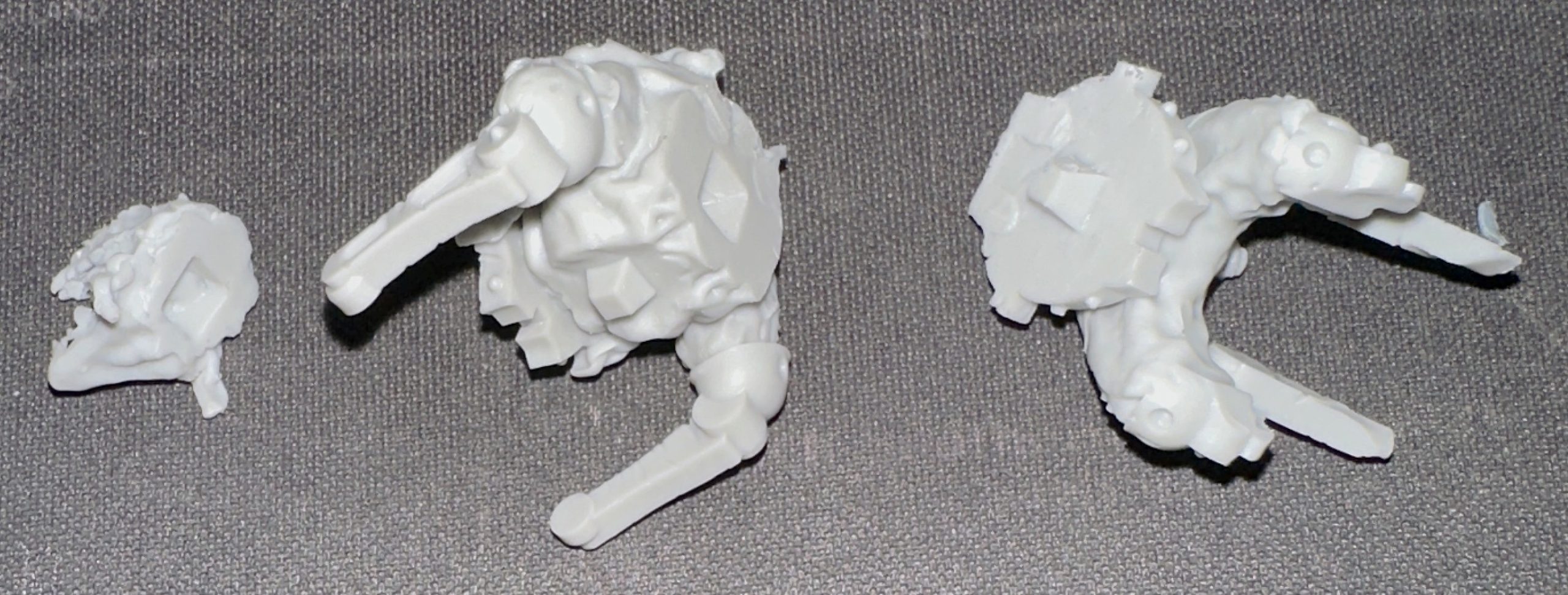
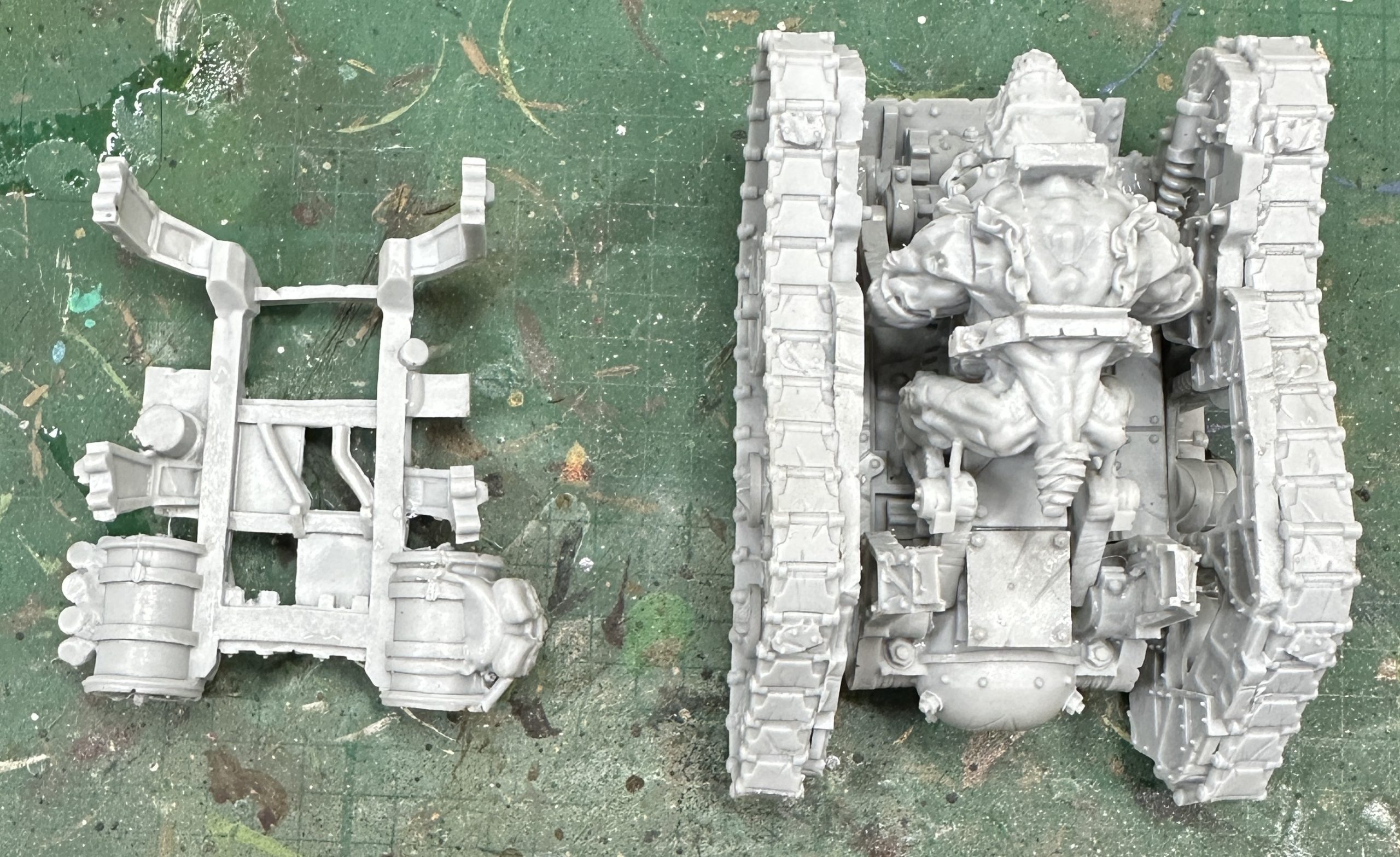
One of the first miniatures I bought was the Death Engine. It is just cool. Probably not a great take for tournament play as although it is quick and has Crushing Strength (2) it is a bit erratic in melee with D6+7 so anything from a measly 8 to a mighty 13 attacks. I opened the box to find a cast resin kit in quite a few pieces:
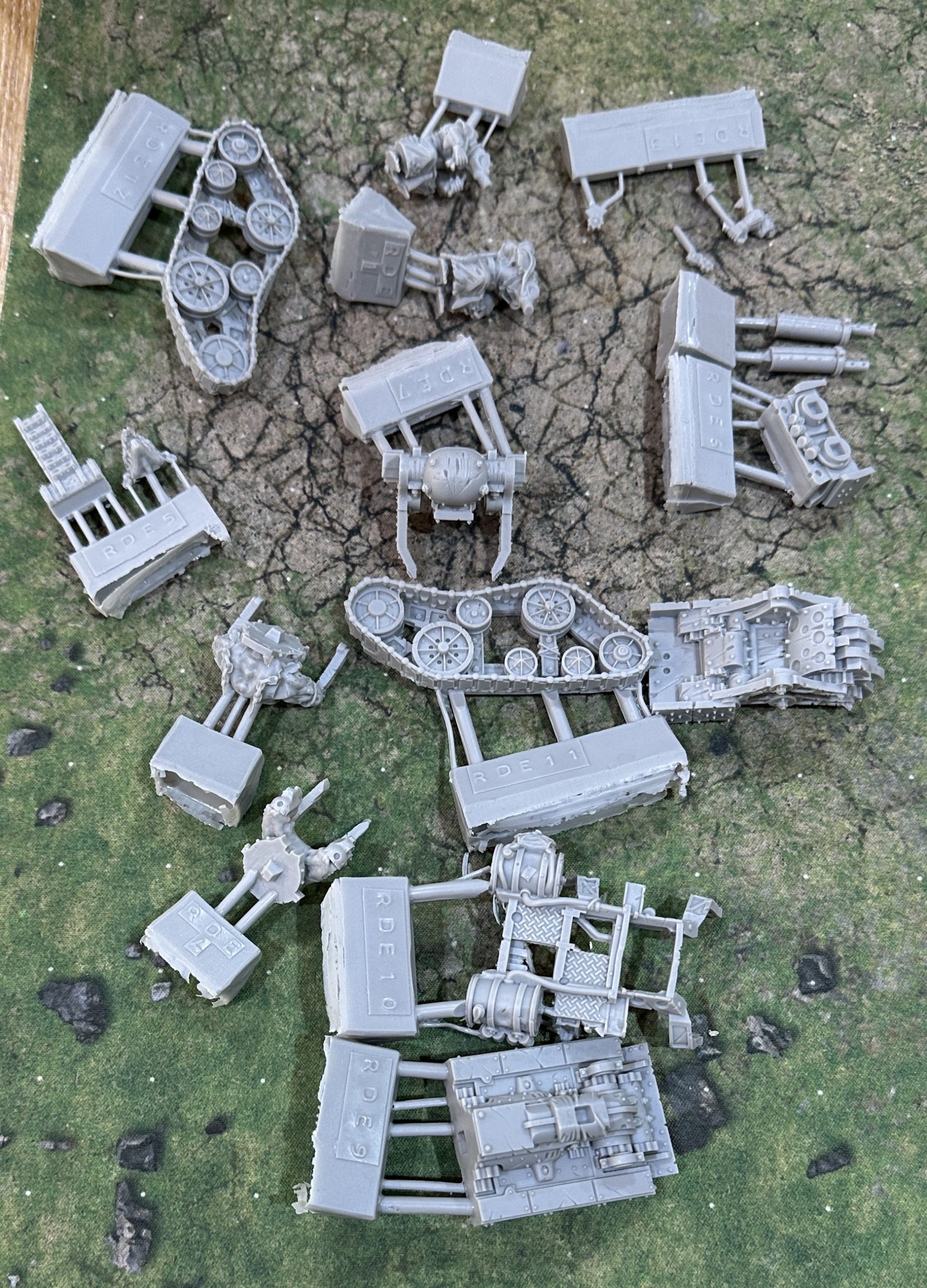
Once clipped off, washed and dried we are ready to assemble. Looked online for the instructions. Mantic haven’t done any. Come on Mantic, be better. This kit has been out for years. Not only that but there is only a photo of it from one angle. So even the ones you built you didn’t bother to photograph from behind. Sadly there isn’t anyone online who has built one or properly photographed either.
This isn’t an easy kit to build and I found it hard even with all my years of experience to call on. Given there isn’t any guidance I’ll try to give as much information on building it as I can here.
The easy parts to identify are the lower hull, tracks and the three parts of the giant rat who powers the Engine.
Lay them out and then glue together with superglue.
When set the two parts are combined by sliding the rat down into position. There are four main connection points. His front leg pistons line up inside the round parts at the front and his back pistons line up with similar slots at the back. You might have to push him down to get him to slide fully into position. I was careful as I didn’t want the resin to snap. He must go right down otherwise the upper hull frame won’t fit.
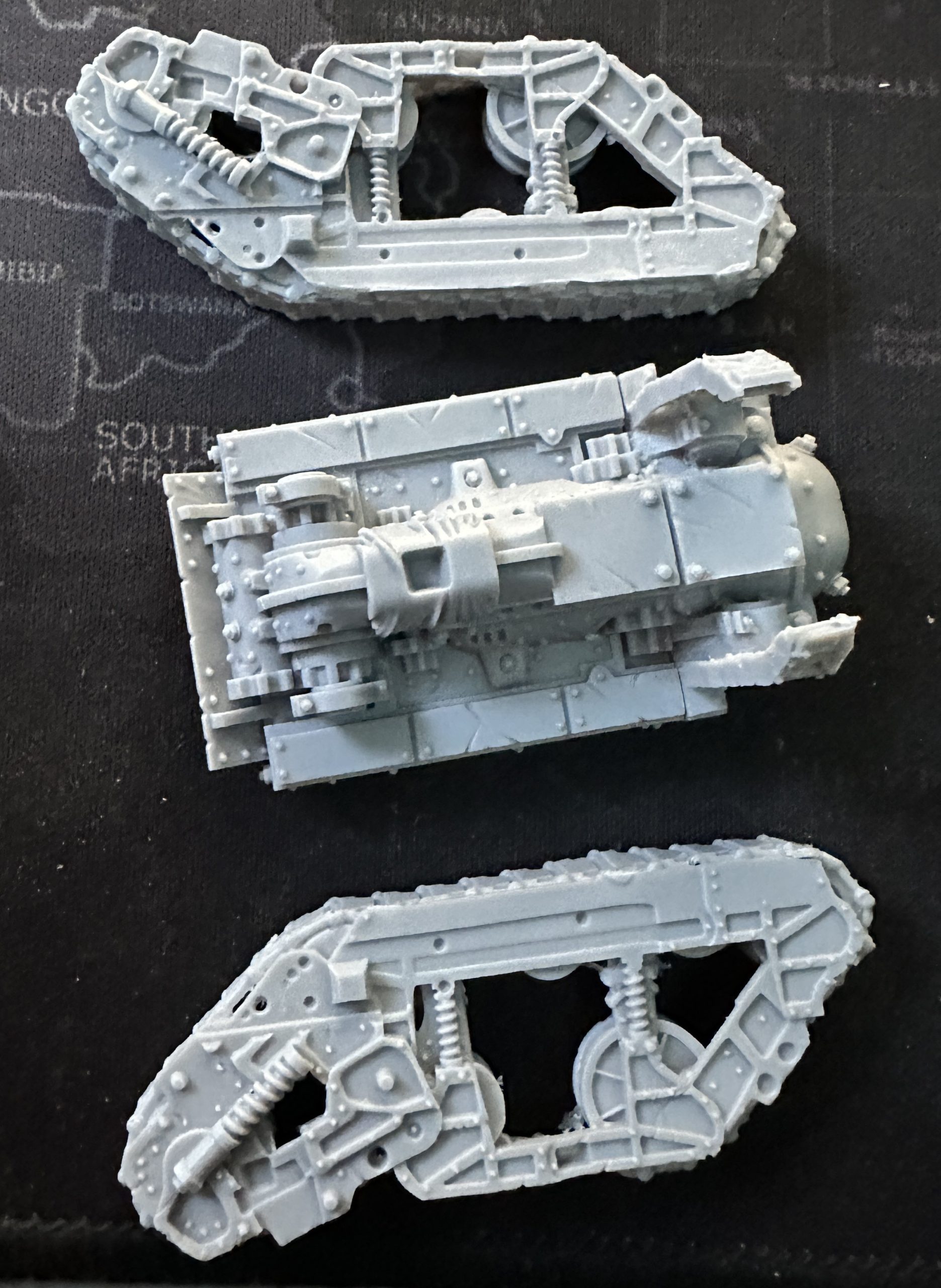
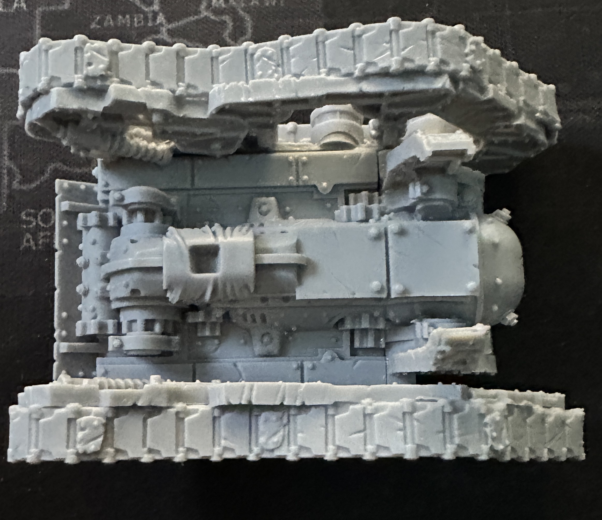
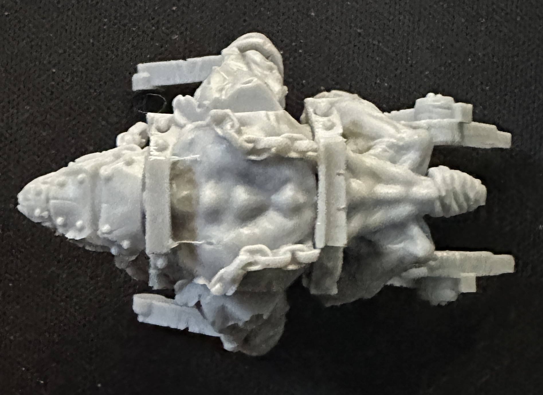
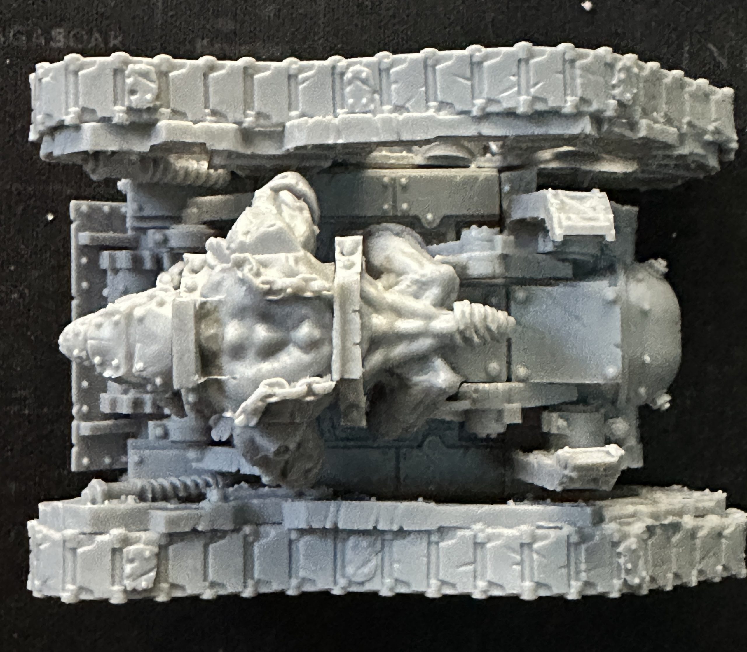
Now the real issues started. Fitting the upper hull is a pain.
The upper hull which is a framework cast in a single piece. Mine was badly warped as it was both bent and twisted and almost impossible to straighten out. This is done by heating the part up in boiled water, twisting back into position and then resetting in cold water.
The trick to getting it in the right position is the rear. With no pictures of this to work from I test fitted the part lots of times until I got it to match the photos of the front as close as possible. At the back the two bits sticking up from the lower hull need to rest nicely on the inner side of the barrels, between the cast details.
Additionally there are lugs on the bottom of the frame ends but no lug holes in the lower frame. It is therefore hard to guess where it should fit. The amount of flex in this piece is not your friend at this point as the front struts can bend into several plausible positions. There are some tempting looking recesses but in the end I chose a slightly more prominent and longer section that was the best to adapt the pieces to fit to.
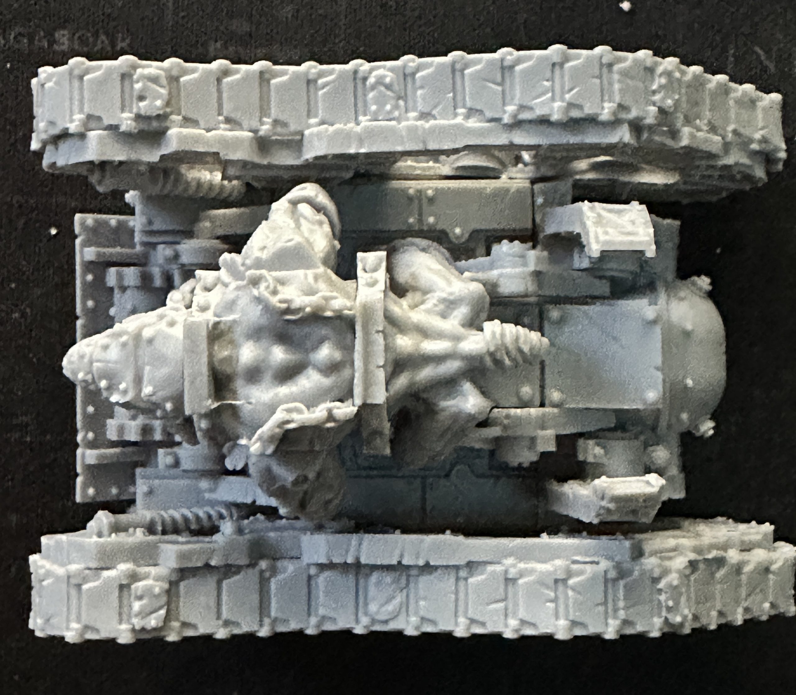
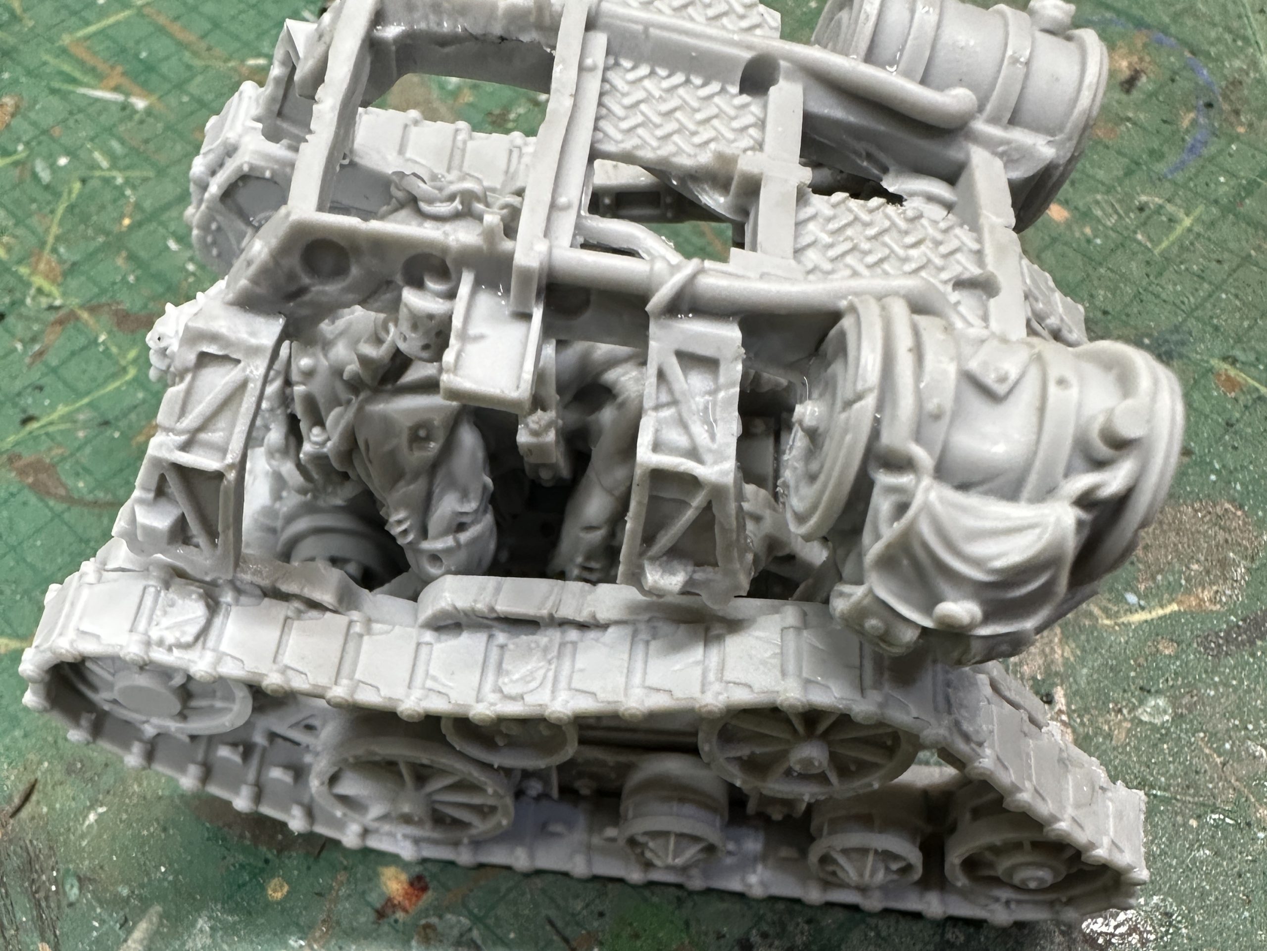
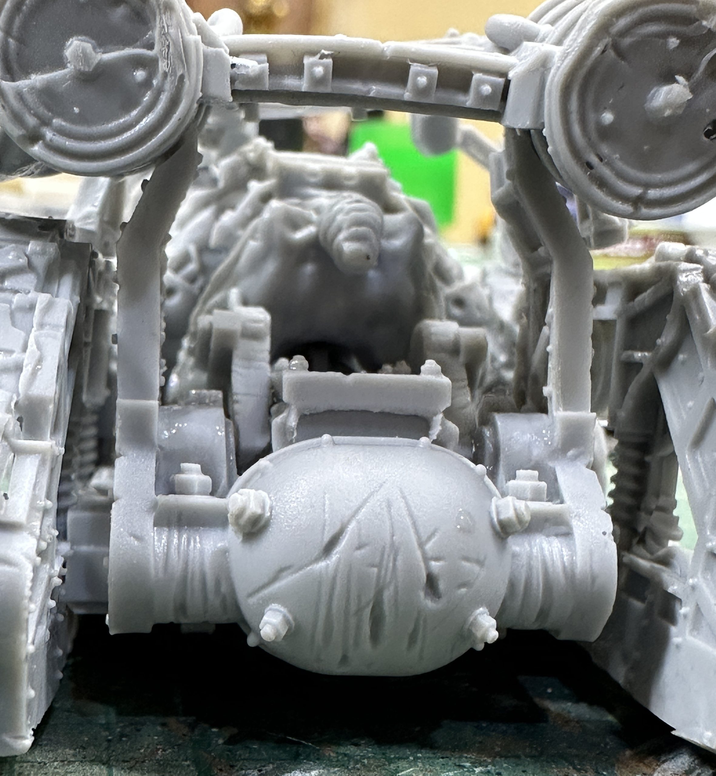
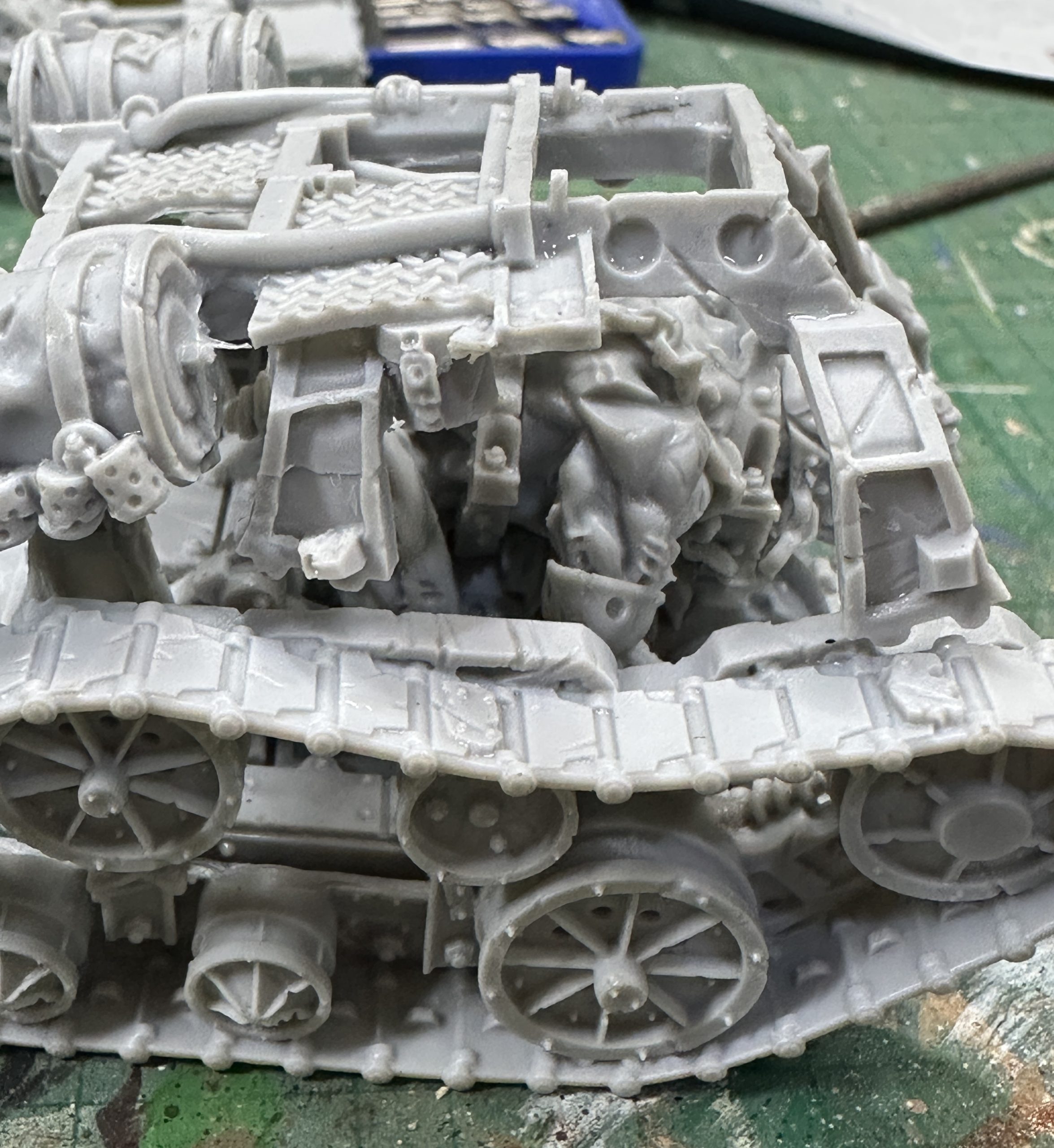
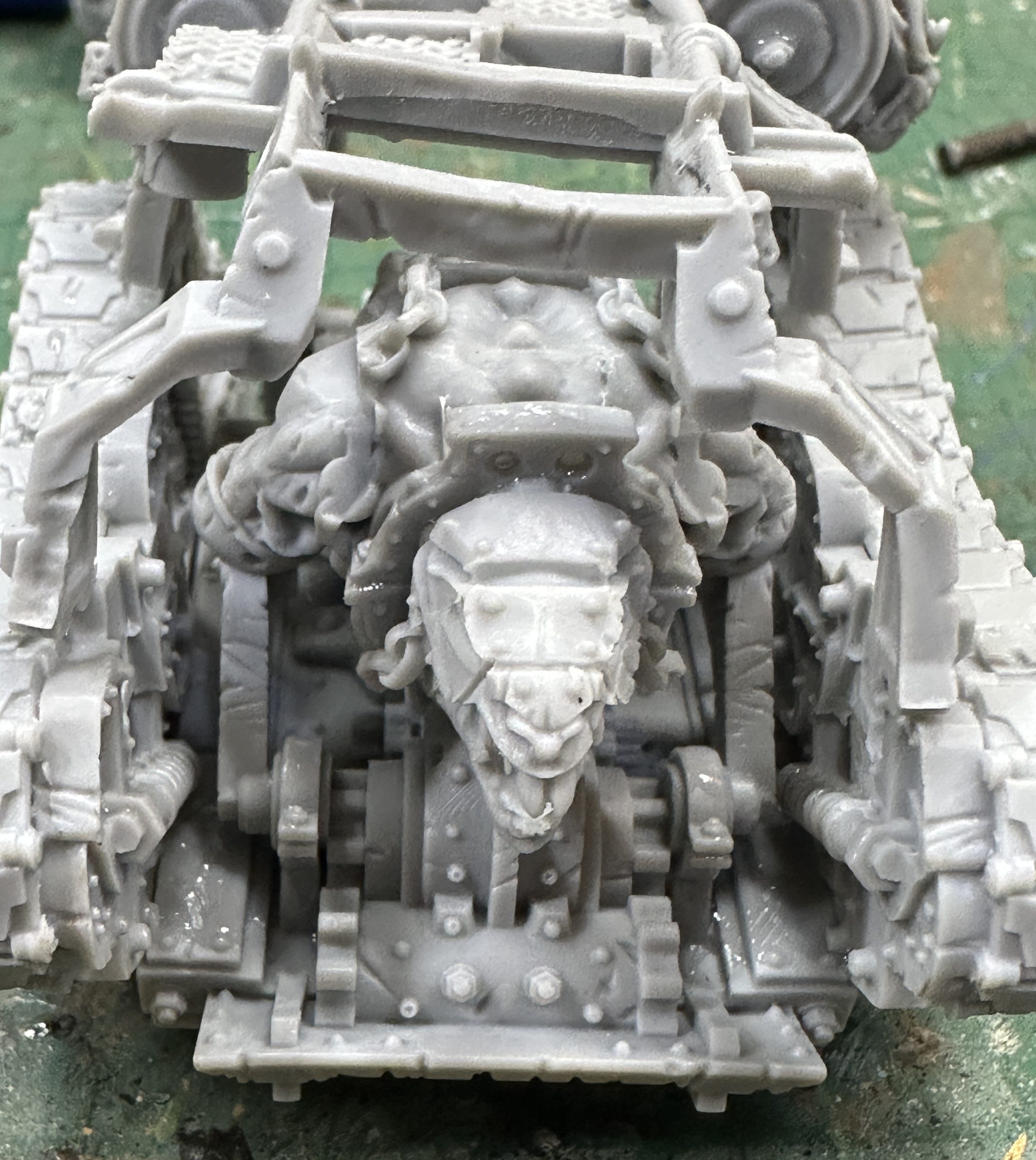
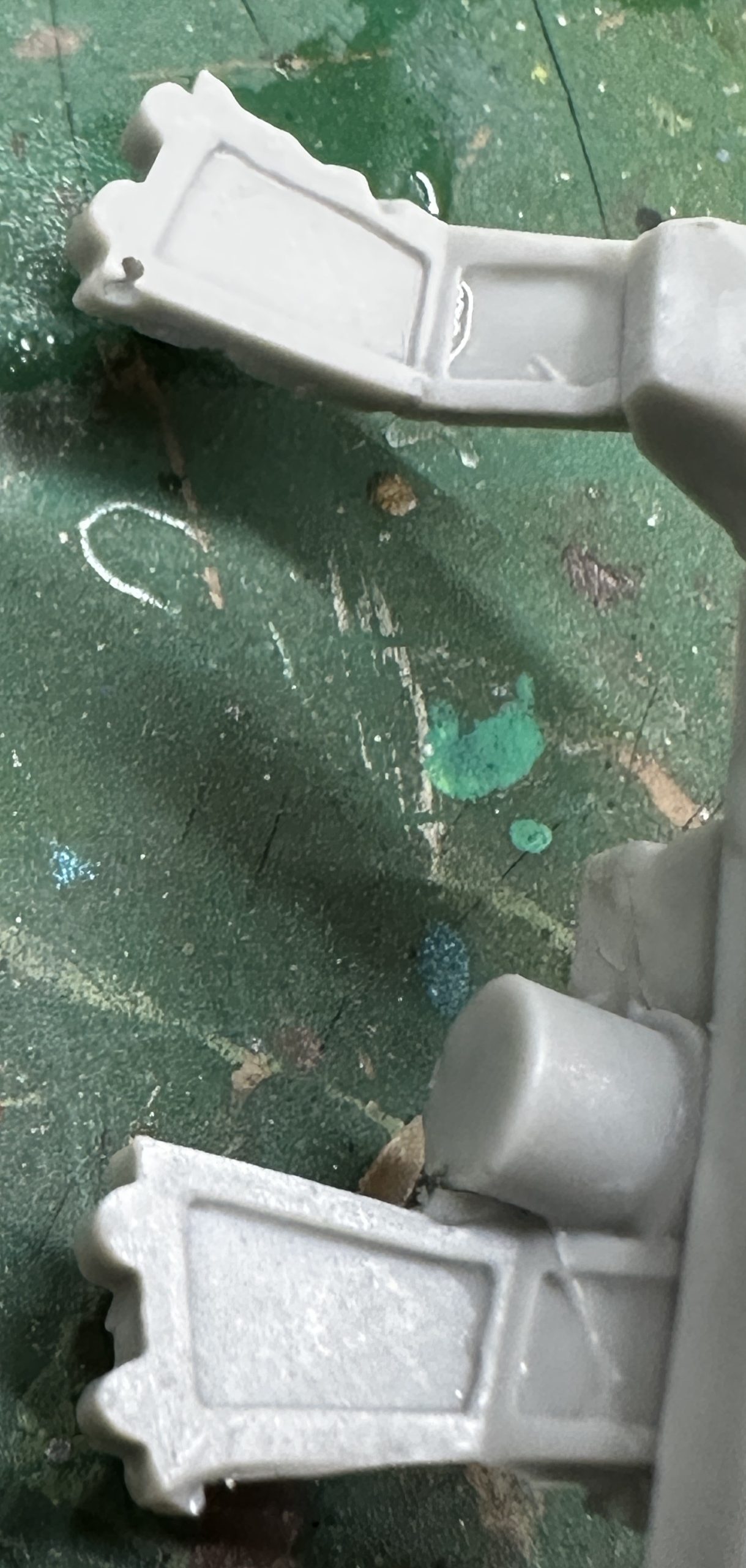
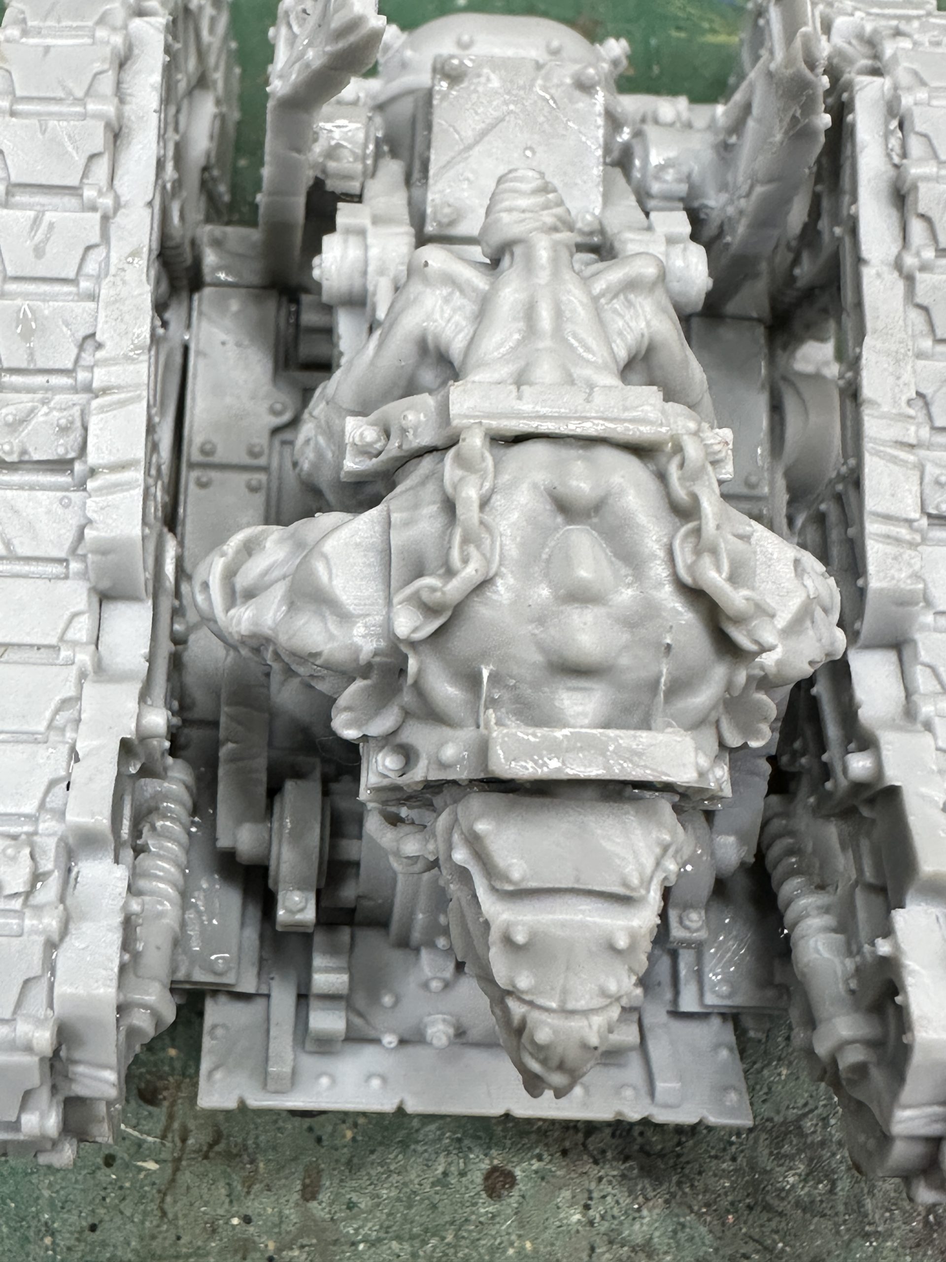
When in position with glue on, mine slipped a bit at the back, due to the twist I hadn’t fully straightened out. It will be okay as it is still fairly flat and the mis-positioning won’t stop other pieces from fitting.
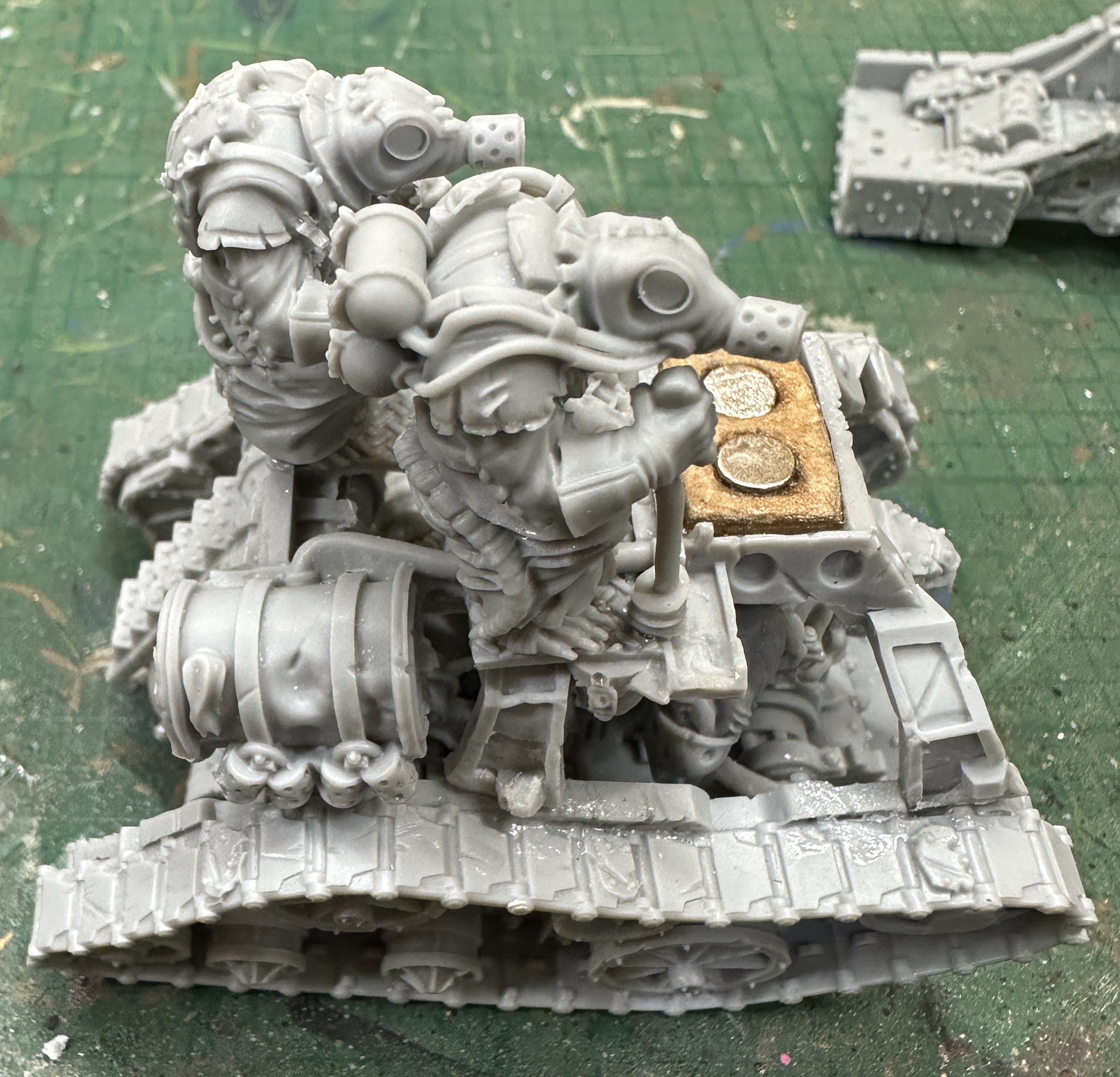
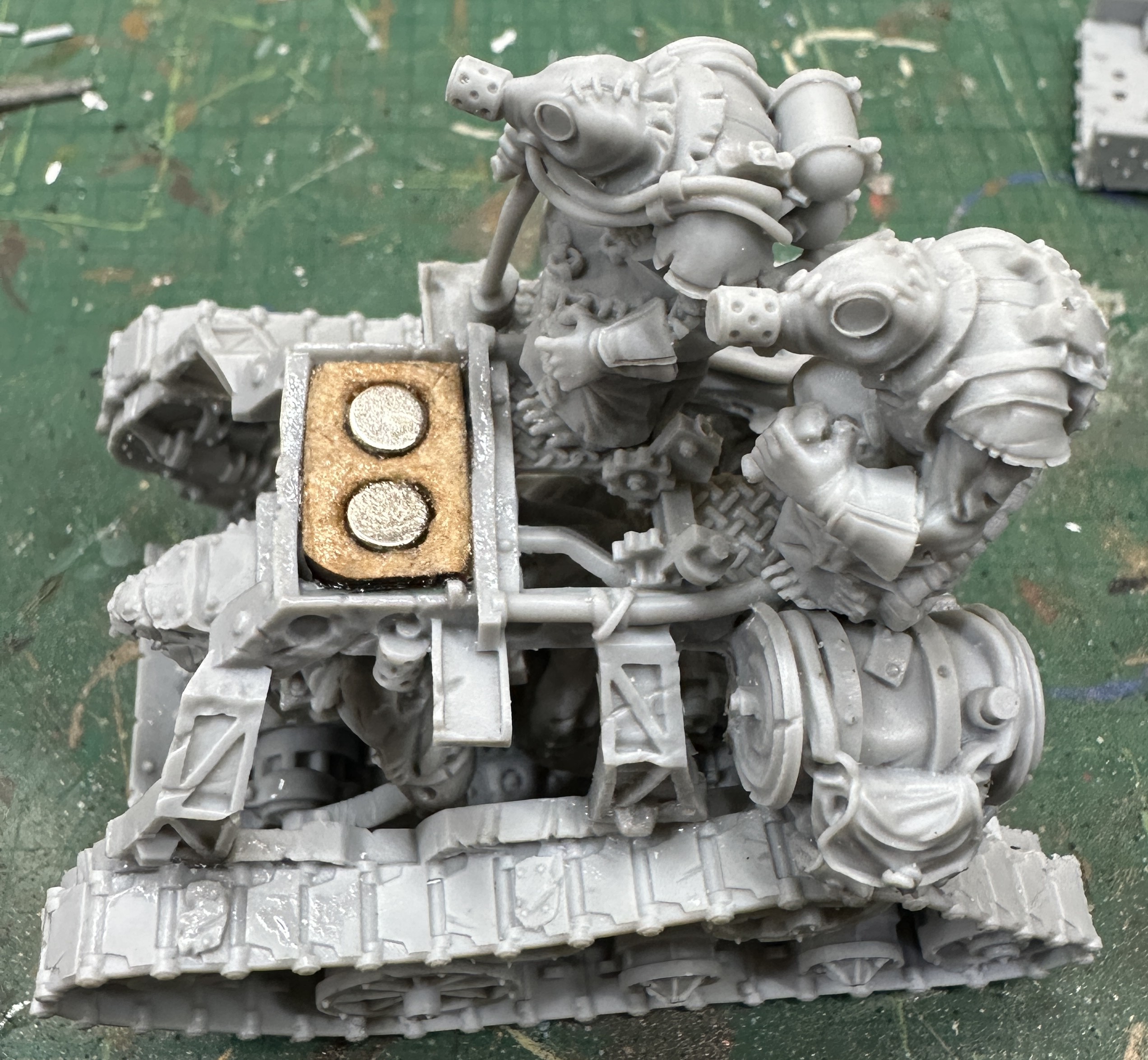
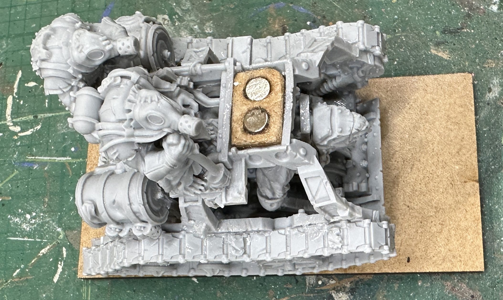
In the end I cut the lugs off the bottom of the front of the frame and filed the angle to match the surface they were being glued to, again different on both sides due to the twist. This took a long time to get right but these photos should save you some time lining it up in the best position.
Once dry you can fit the steps. There is a groove in the barrel that fits under the upper frame strut. Mine is a bit wonky due to the slip when gluing and twist in the frame. Still fits fine.
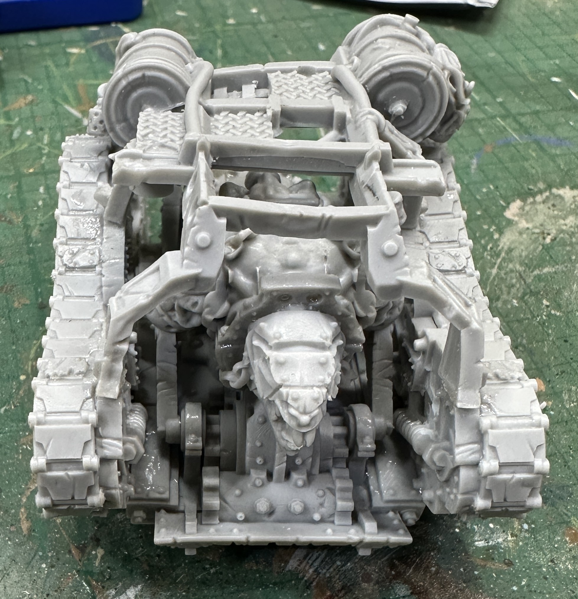
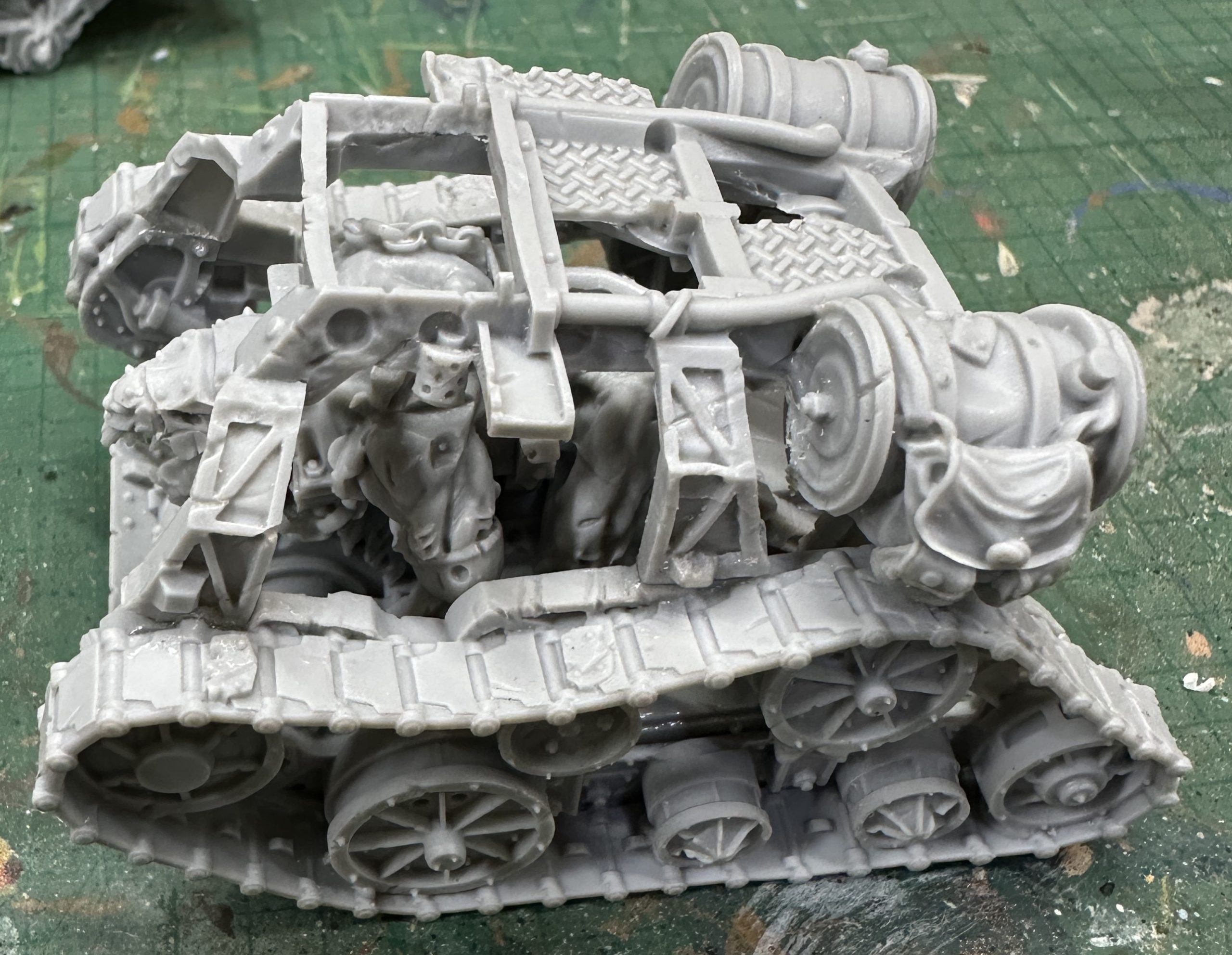
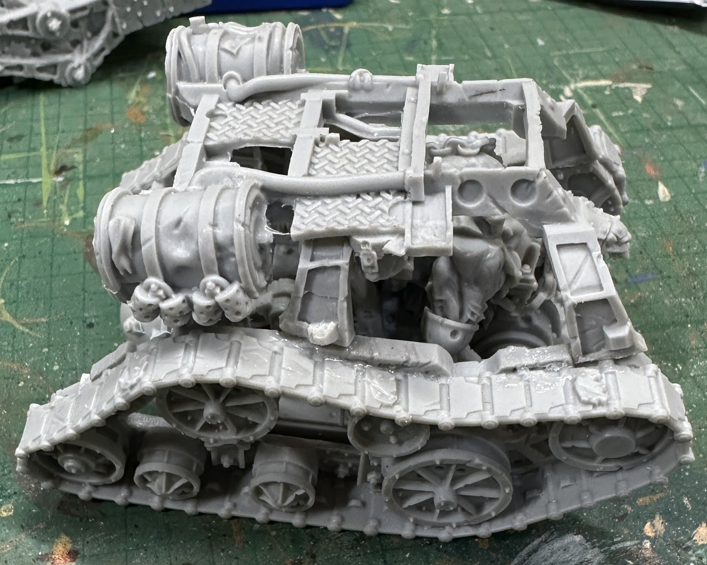
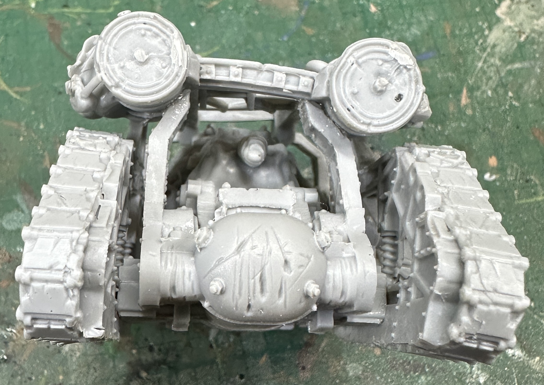
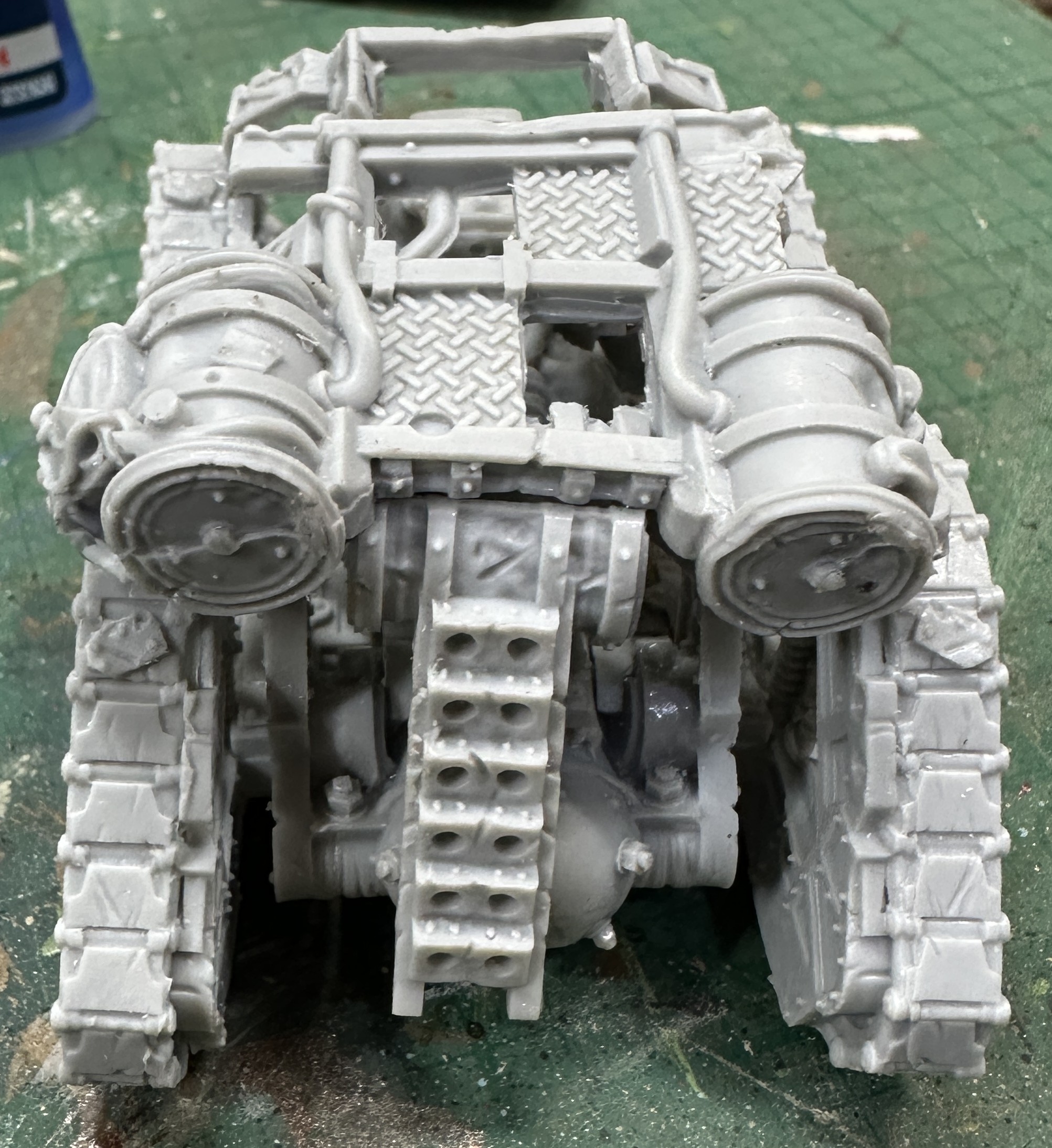
With that done I went on to magnetization. The Death Engine comes with two alternate builds, a shooty one with dual machine guns and a melee one with a big spinning mangler. I want the option to use both so magnets are the way to go.
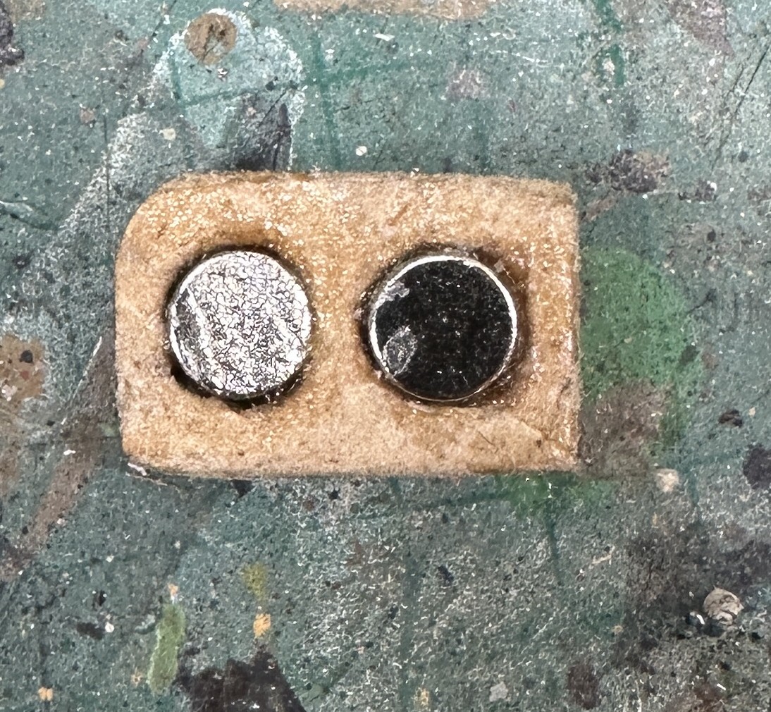
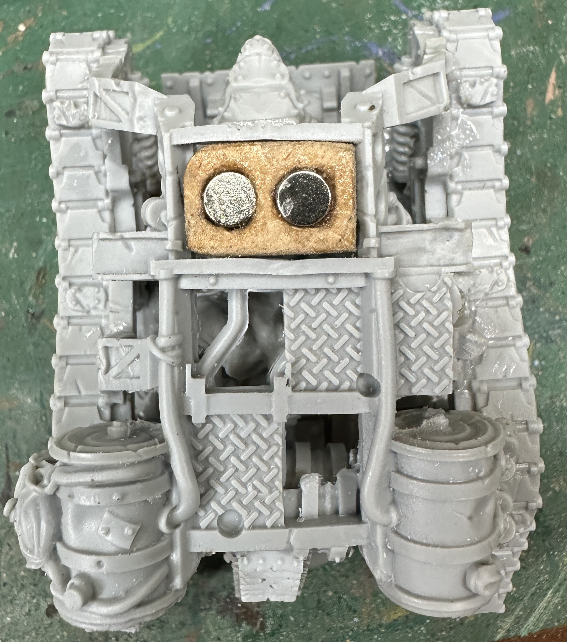
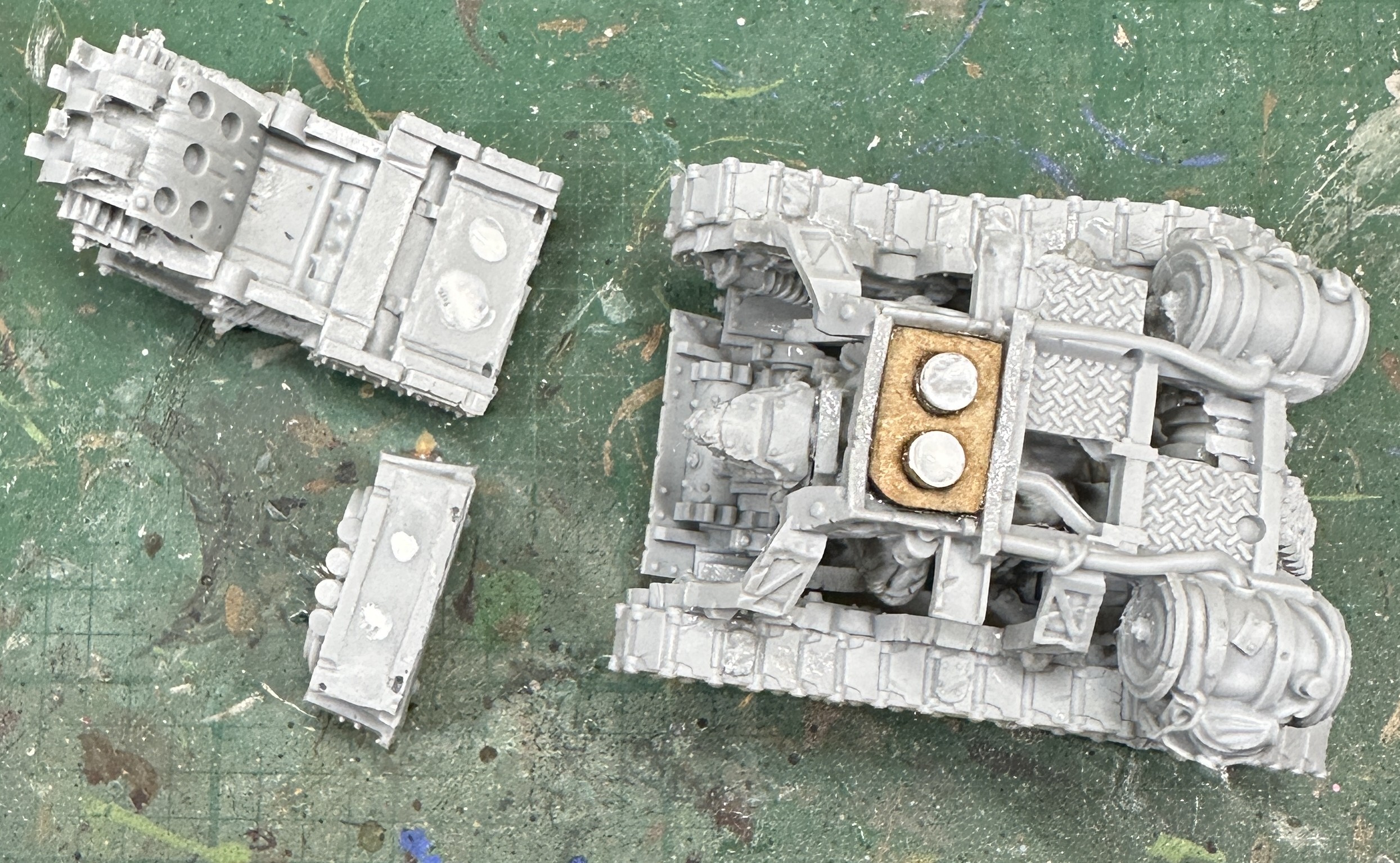
Unhelpfully the hull section that the alternate pieces fit onto is just a frame. There needs to be a solid part inserted inside this to house the magnets. I used an off-cut of 3mm MDF that I shaped to fit snugly. Holes were drilled in this and two magnets fitted. It was glued into place with superglue.
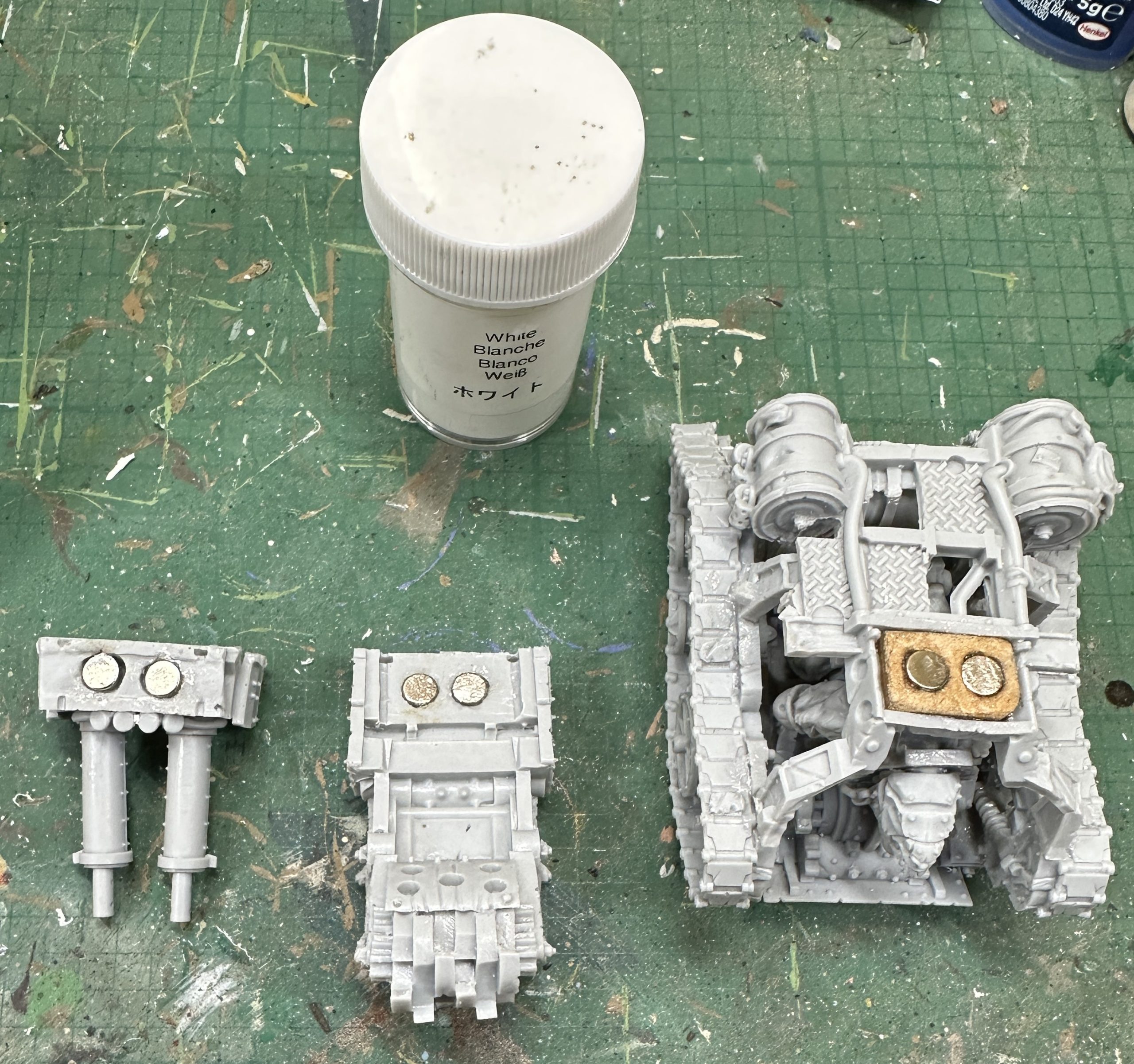
To transfer the exact position of these magnets onto the two interchangeable pieces I used a thick white paint that was blobbed onto the magnets and then the pieces were fitted on top, transferring the paint. Holes were drilled and magnets inserted, carefully checking they were the correct way round before gluing into position.
Now we can neatly interchange the two build options.
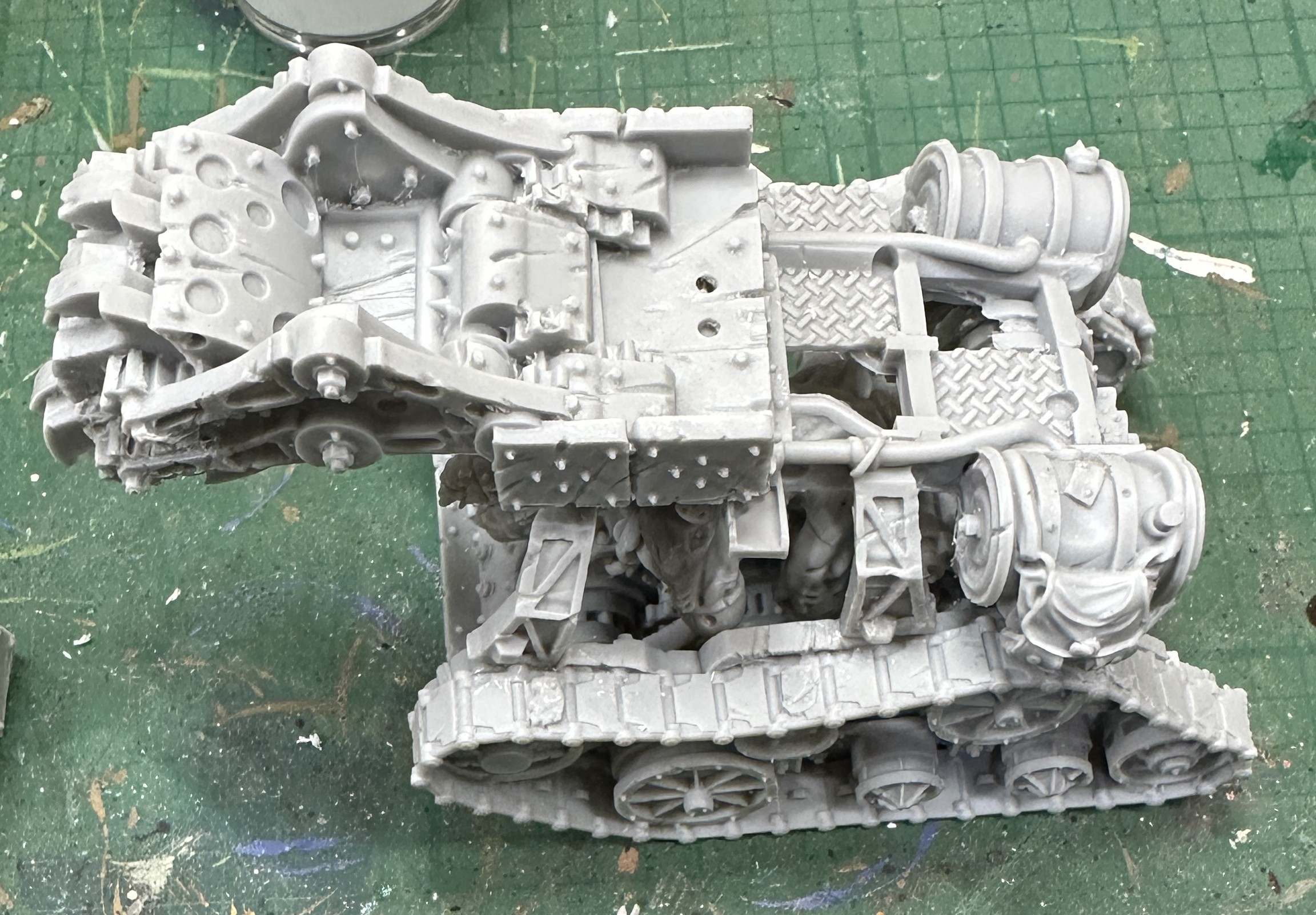
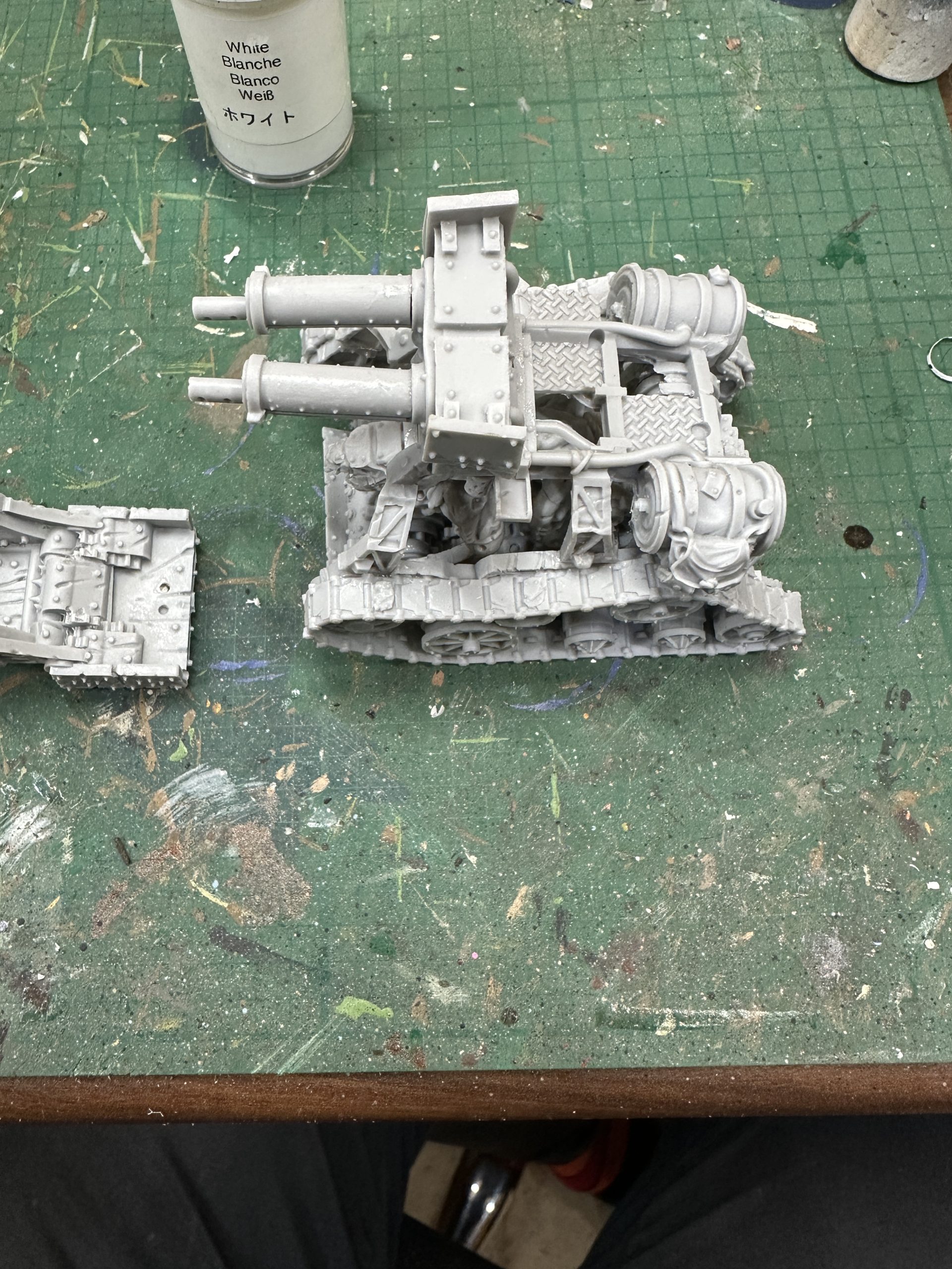
Finally the two crew and the control mechanisms. I have a feeling I cut off some cables for the driver that were supposed to connect his hand grip controls to the gears in the floor. They were next to some resin vents that were the same thickness so it was an understandable mistake. I’m not unhappy with their loss. Parts like that are vulnerable to breakage on a gaming piece so I’m fine with them being missing.
There is no clear point to fix the bottom of the weapon operator’s control gear stick onto the floor grating. I checked it didn’t catch against both interchangeable pieces and went with the position shown.
Finally glue the model onto a base. It only just fits for width. Remember to allow room at the front for the mangler arm.
And relax, we’re done 🙂