


Build an LED Arch Hobby Light


Recommendations: 34
About the Project
I want better lighting on my project desk, so I have opted to build an LED arch light for maximum light and maximum shadow reduction.
Related Genre: General
This Project is Completed

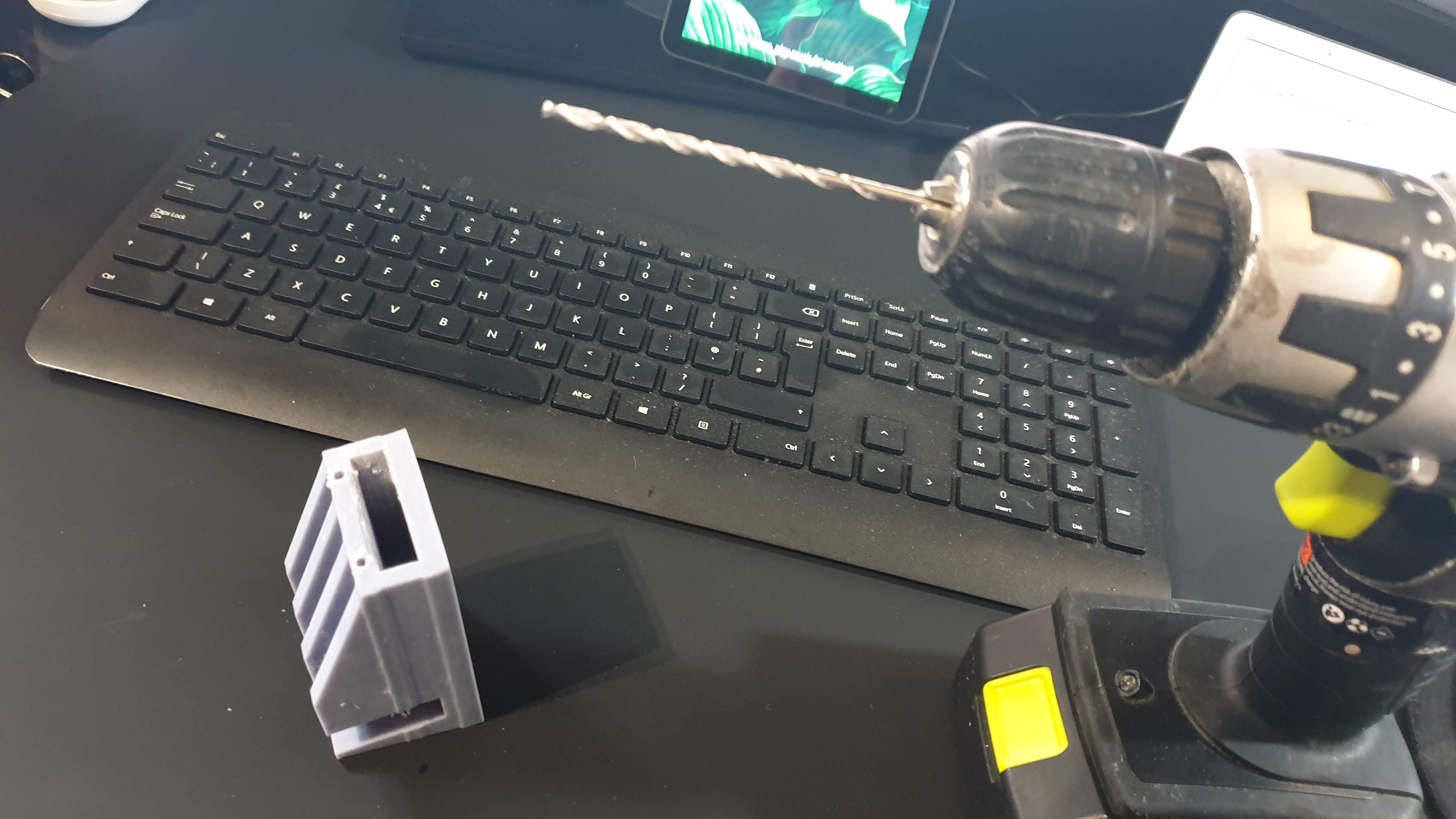
First test pieces are out
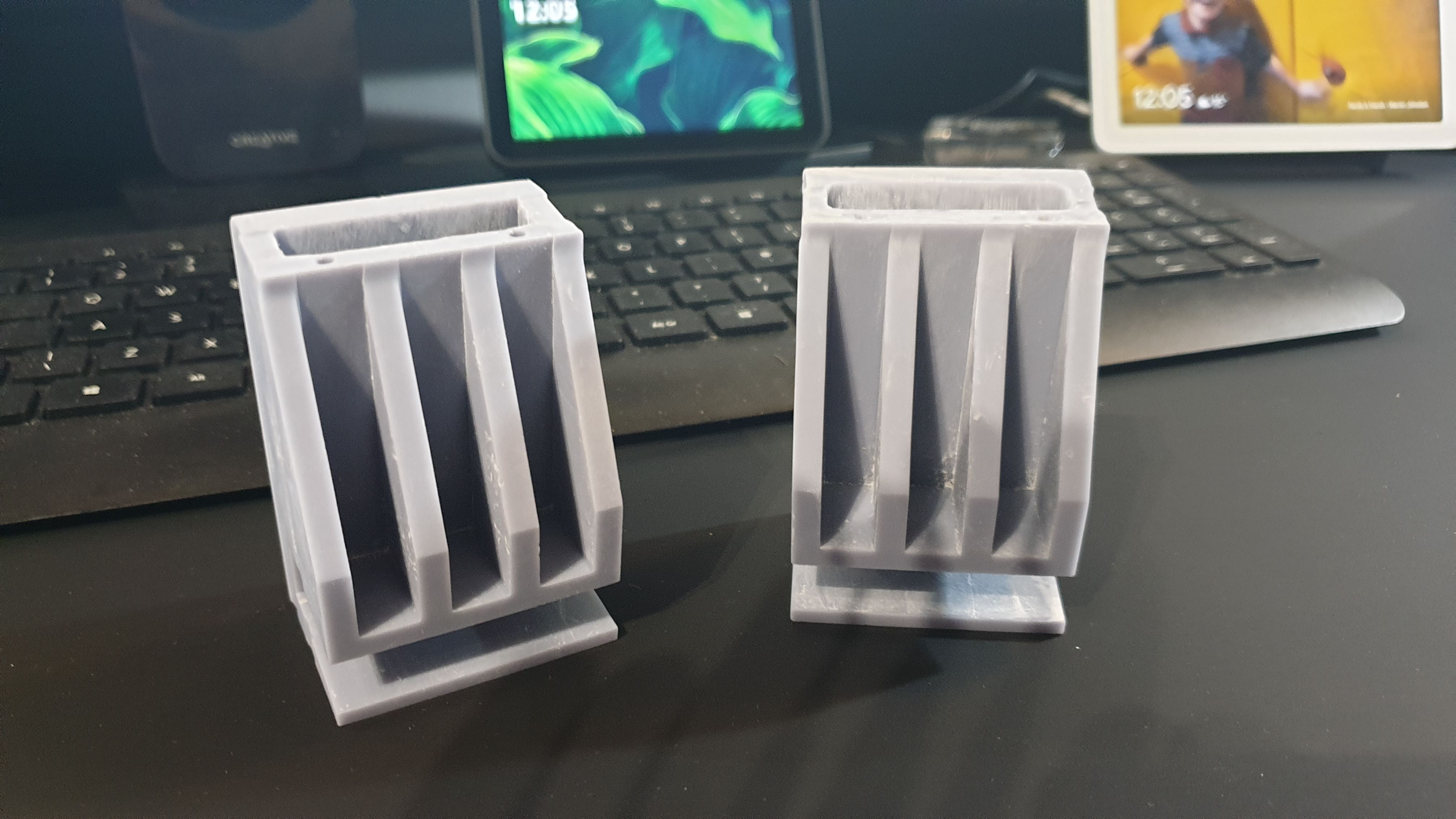

So I printed two test pieces each one took just under 8 hours to complete. There is a strange deformation in the print but I will deal with that later.
The holes for the wiring have also deformed a bit so I will drill those out on these pieces just to keep the process moving so I can pull together a rough concept.


Applying the LEDs
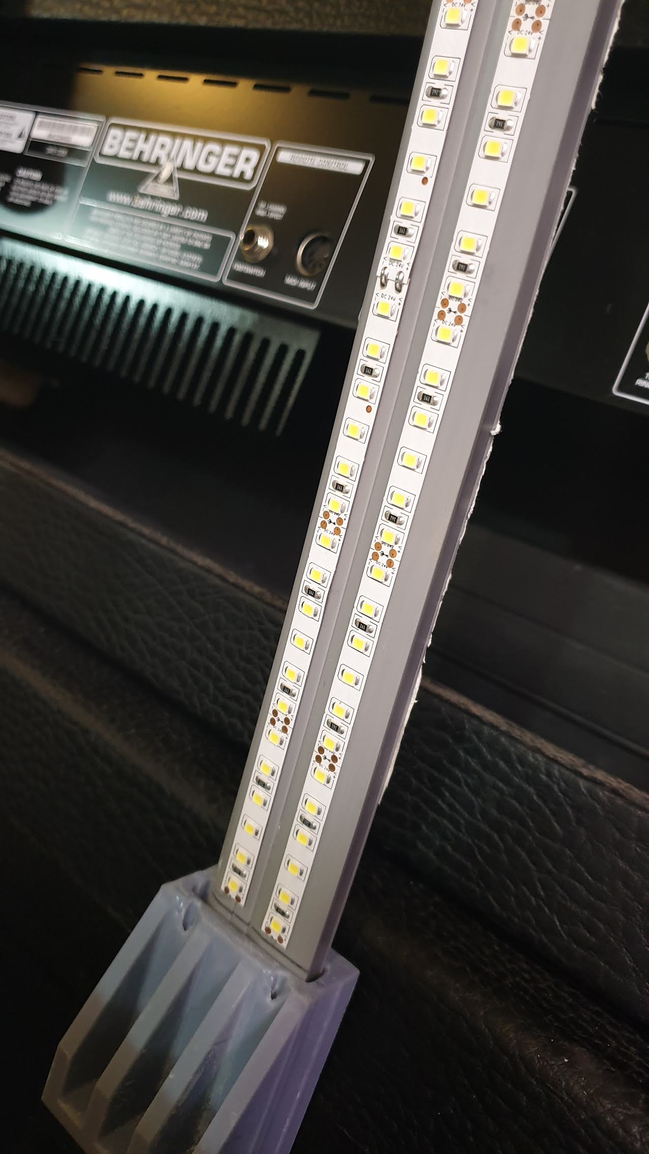
I found that adding the LED’s to the strip must be done while it is bent in place. Otherwise if you add them when it’s flat they curl up on you when you bed the strip.
For this concept piece, I decided to add two strips, for an ultra amount of light. So in total, I used about 5m of LED strip.
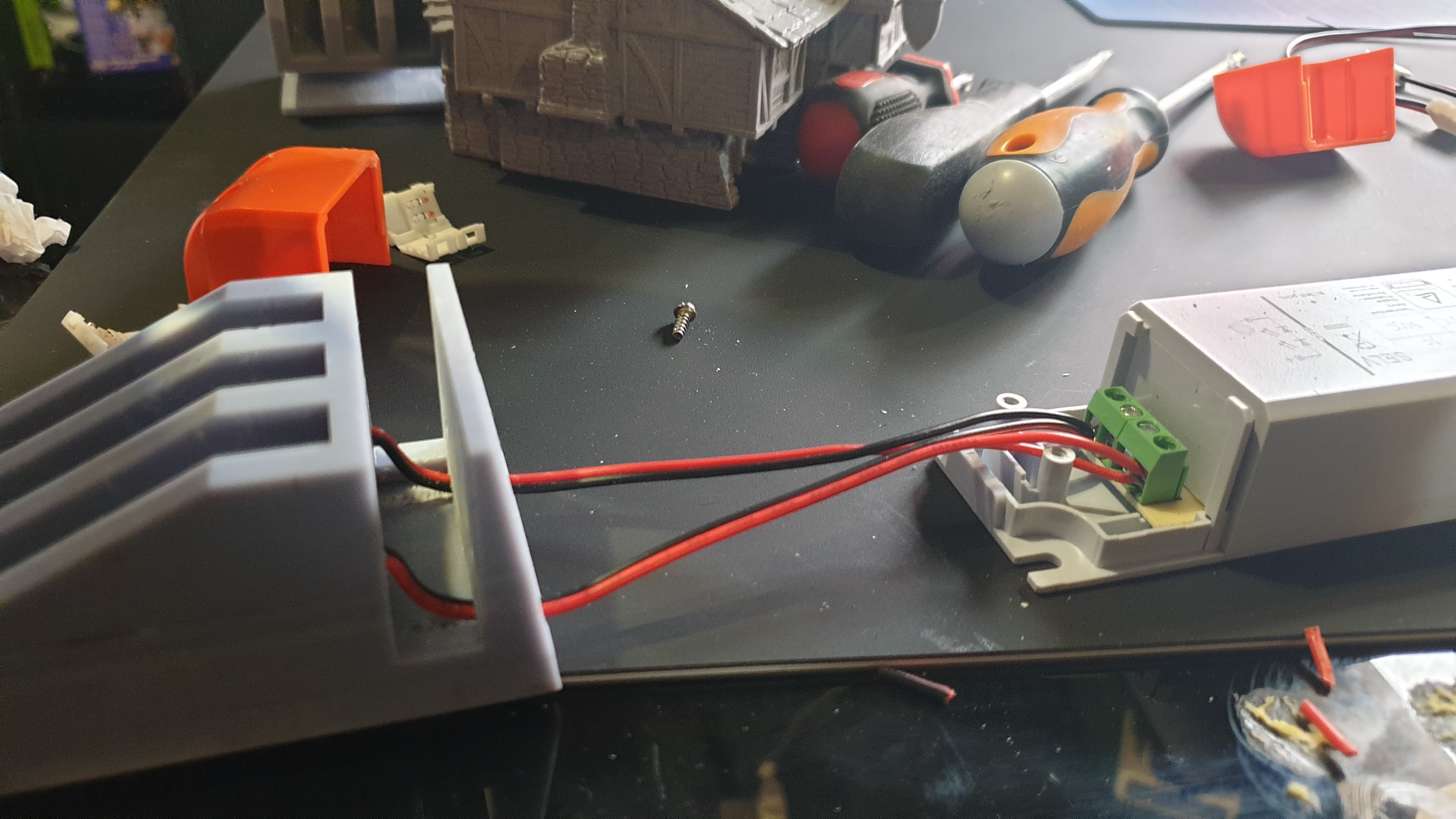
Connect the trips to the power
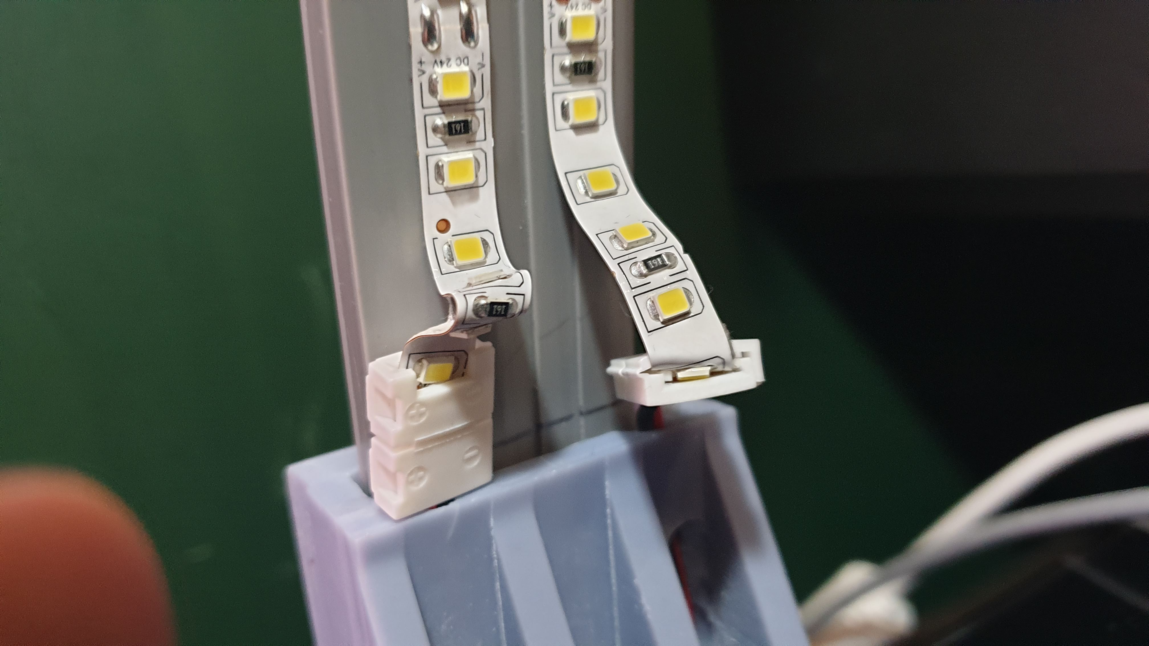
This I found to be VERY fiddly. The little connectors seem like a good idea but in practice, they are not very effective at all. But for the purpose of testing the idea, they will do. But I’m going to have to rethink this as I’m not happy with them at all.
But…
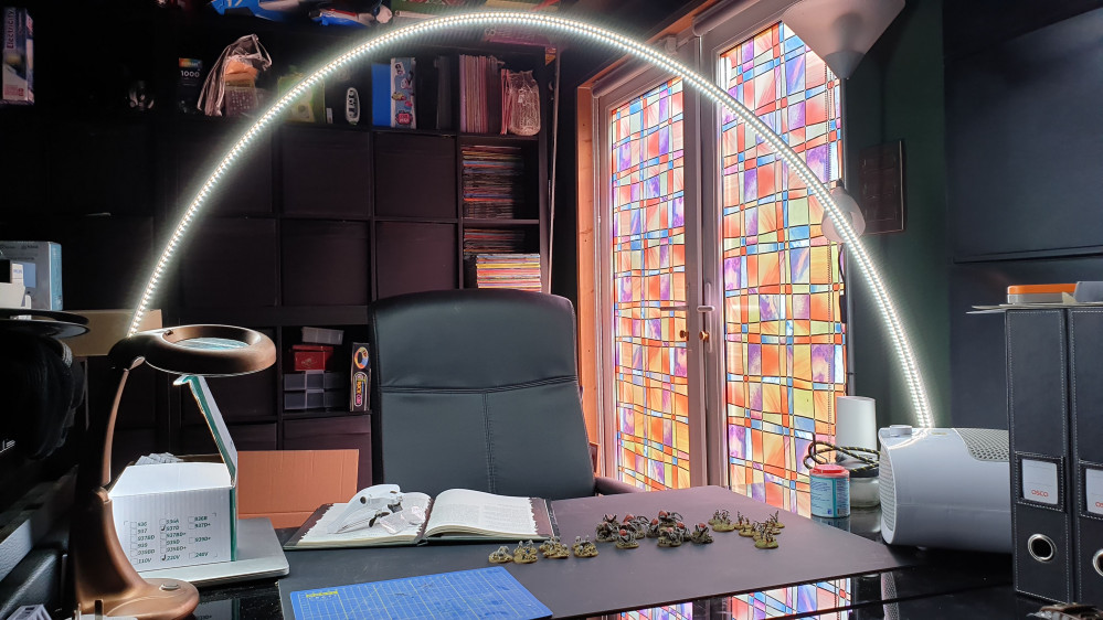
Lets switch it on and see what happens!
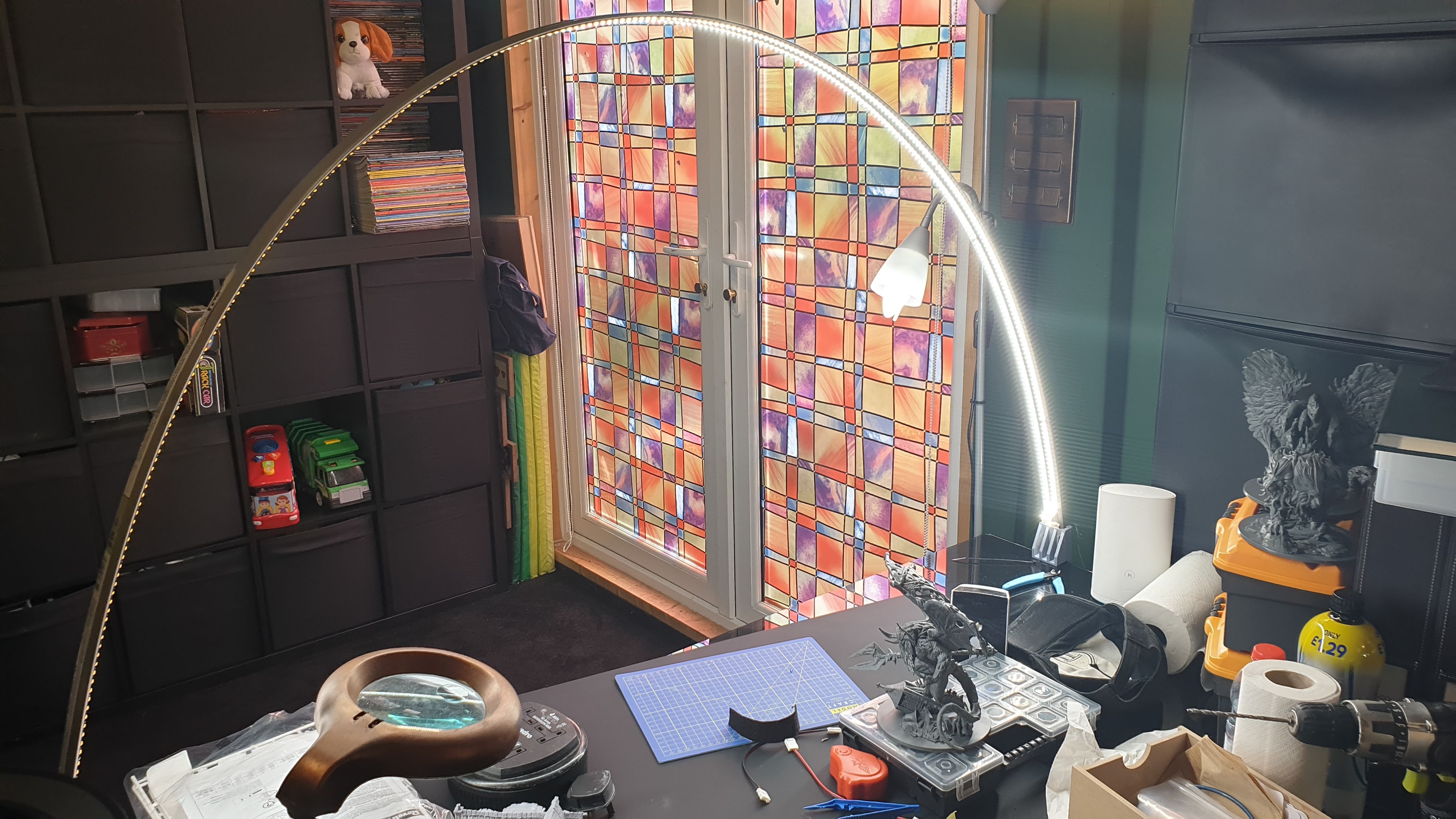
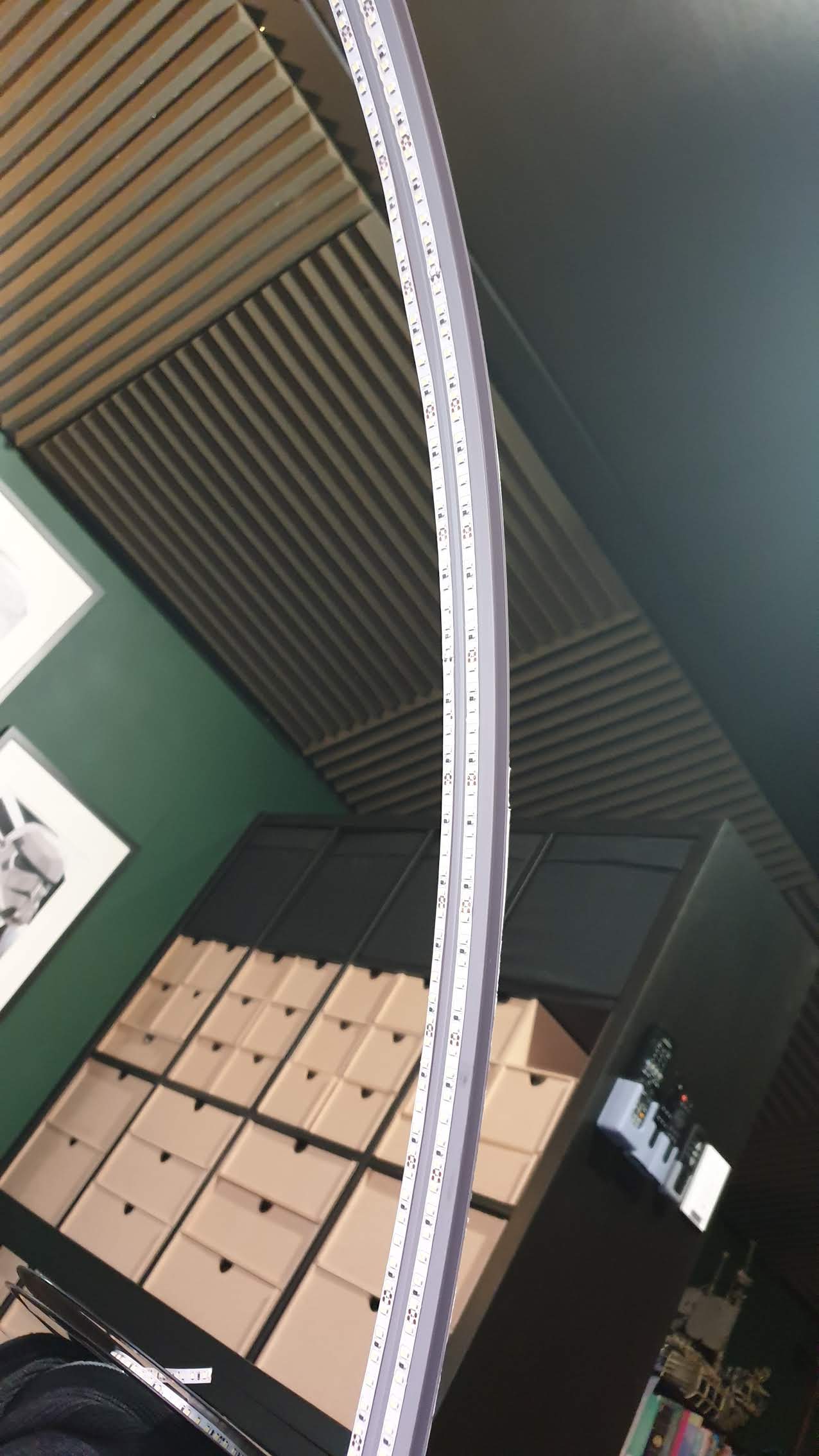
TaDa!!!!!
It’s alive!!!
Ok I’m happy with that as a concept, but the wiring is not what I want… I’m going back to the drawing board to rethink how I’m doing this. I may need to take a leaf out of @blinky456 book and use a soldering iron! Which reminds me – he left one here for us to use mmmmmm….. am I brave enough….
Lets start by re-wiring.
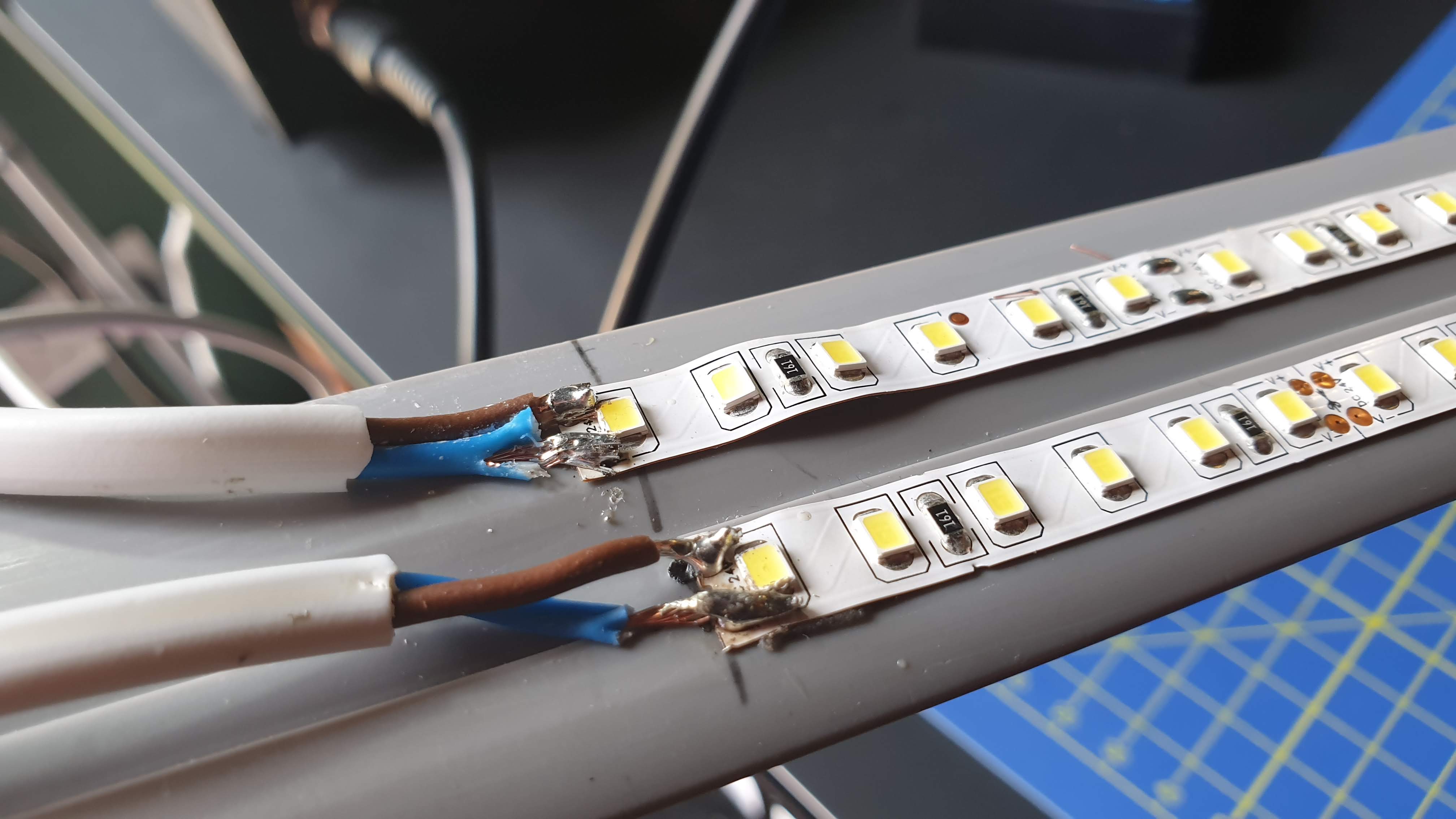
OK, so I need a better wiring setup. So I’m going to have a go at soldering. I’ve already drilled into my finger on this, so hey whats a few burns for the aspiring DIY guy eh!
First things first I’m going to change the flex, so I can make the connection to the power block longer (this will give me a bit more flexibility).
I found this relatively light 2 core laying around.
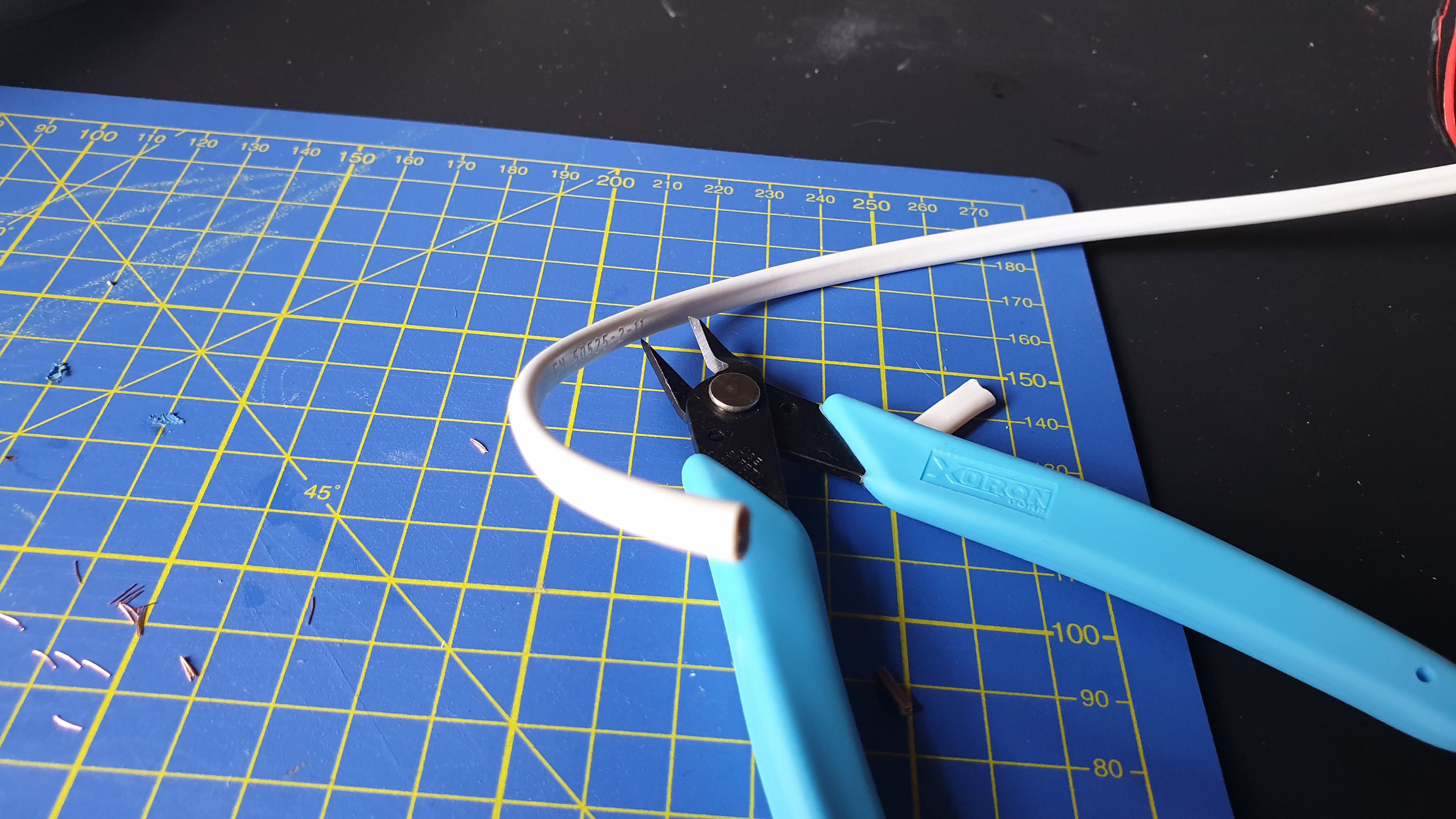 Two lengths of about 40cm each should do.
Our mate blinky left behind a soldering station, so I have nabbed that and will fire it up to see how it works!
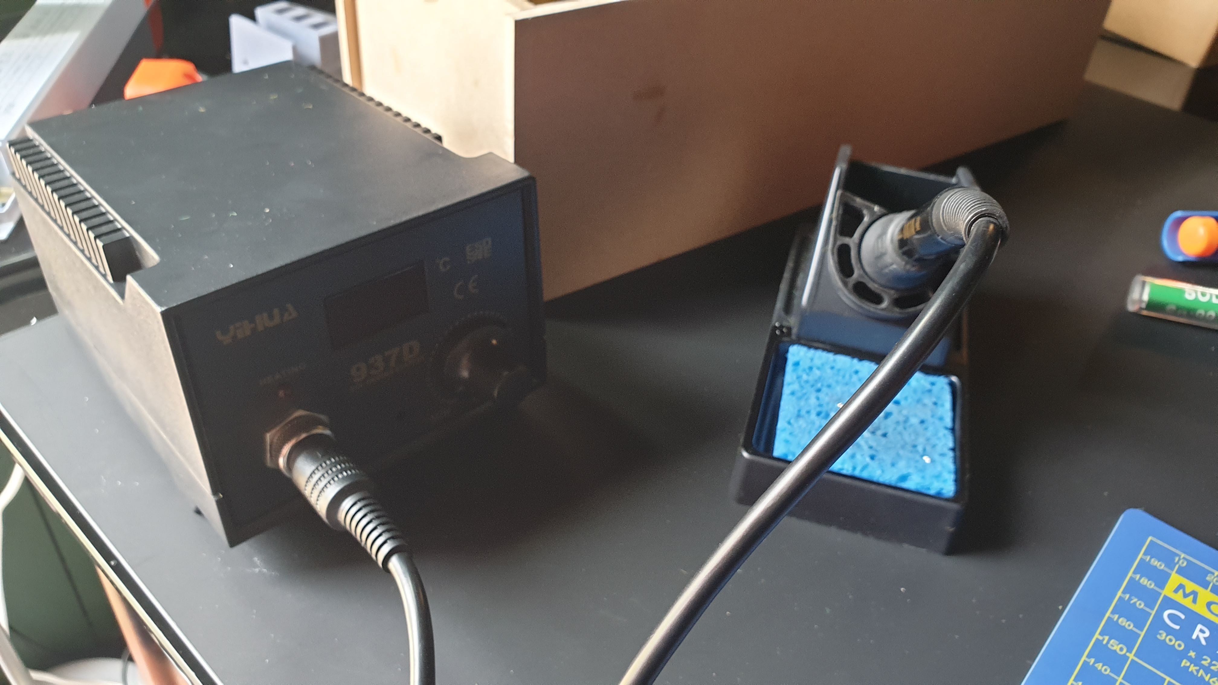 Ohh I Like the Big Knob!
Well, this turned out to be tricky! Trying to hold two bits together while also trying to hold a soldering iron and the solder is no easy task.
But it’s on, its not pretty but it is soldered at least! I will have to read up on soldering techniques and give this some more practice. Maybe I need to buy a set of those helping hands things? or a little set of clamps.
Suggestions welcome folks!
 Yeah Yeah Yeah - I know its a bit of a dogs dinner!
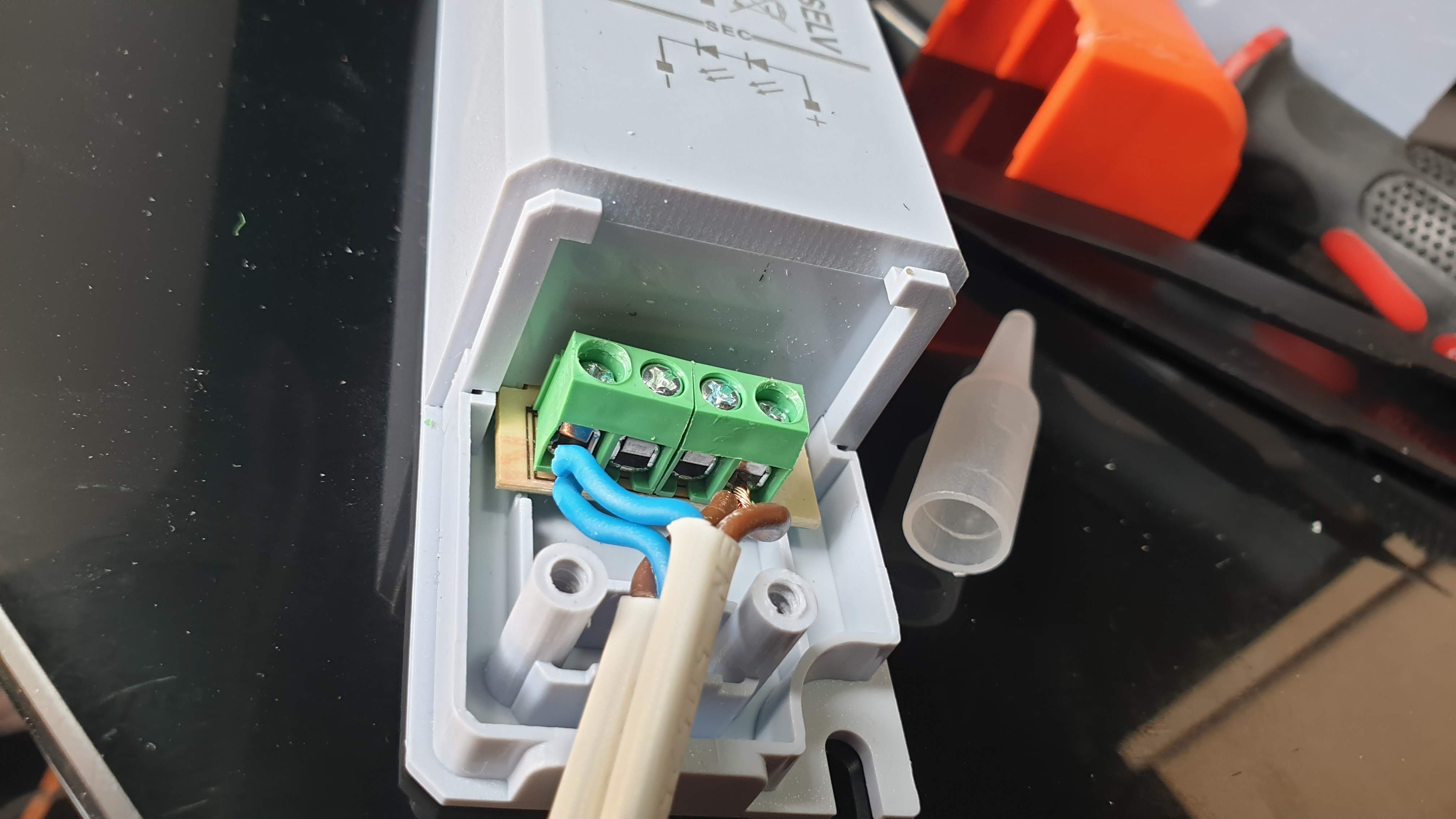
OK now I’m going to join the wires at the other end and put a drop of solder on them to lock them together and screw them into the power block
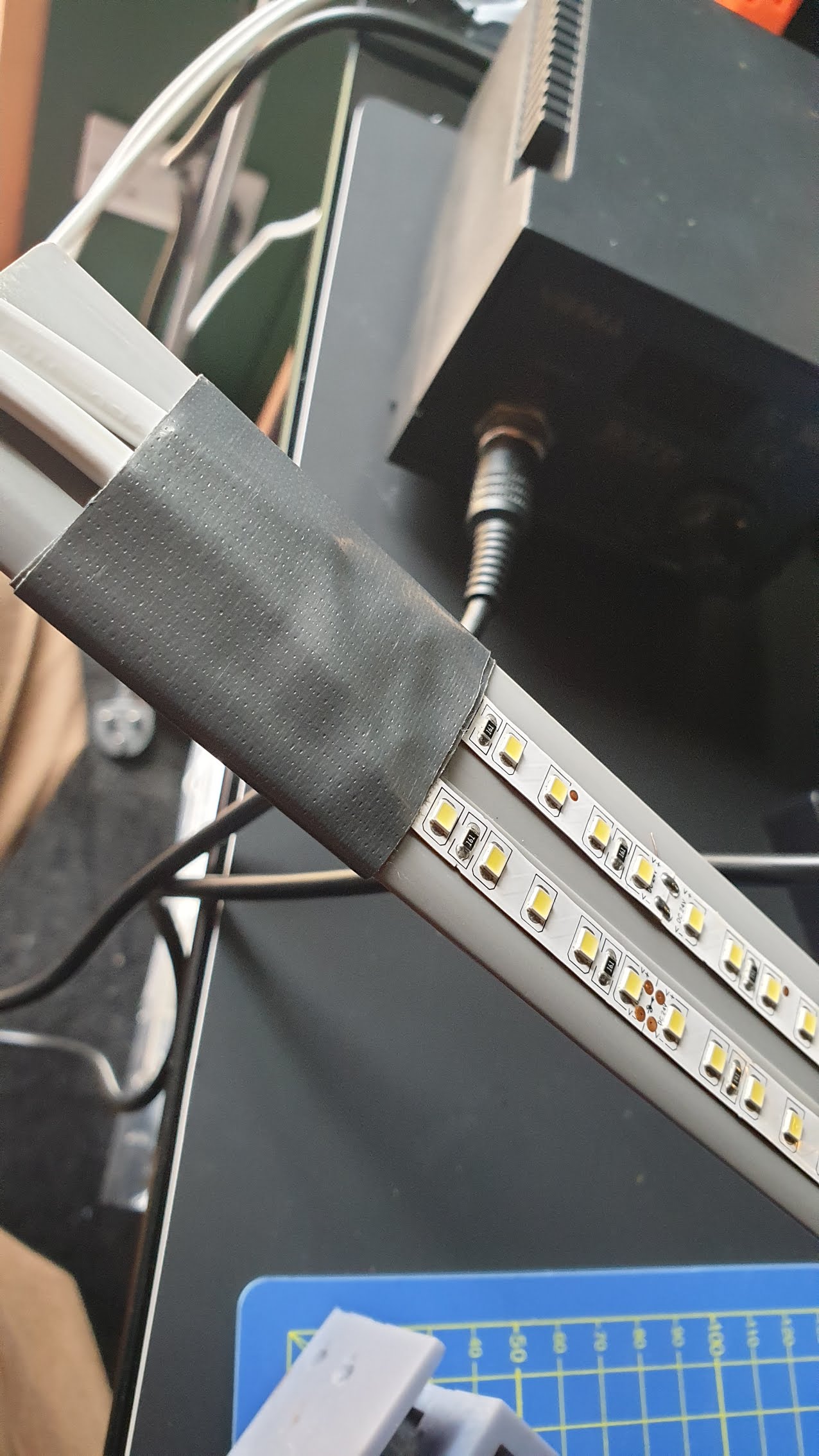
And finally to add a bit of T-REX Tape around the join to keep it a bit tidier…
But now I’m gonna have to redesign the mounts to take into account the extra thickness!
OK Back to TinkerCad!
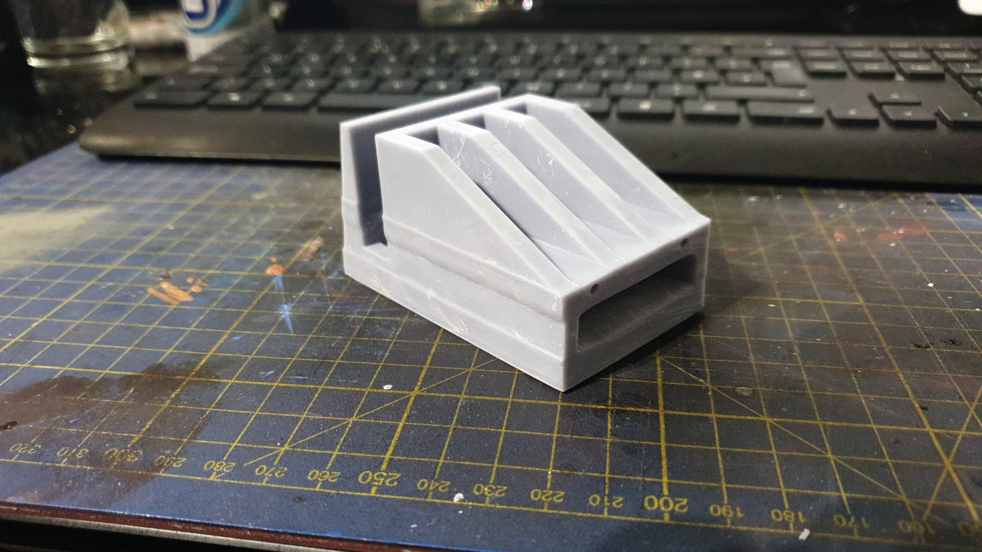
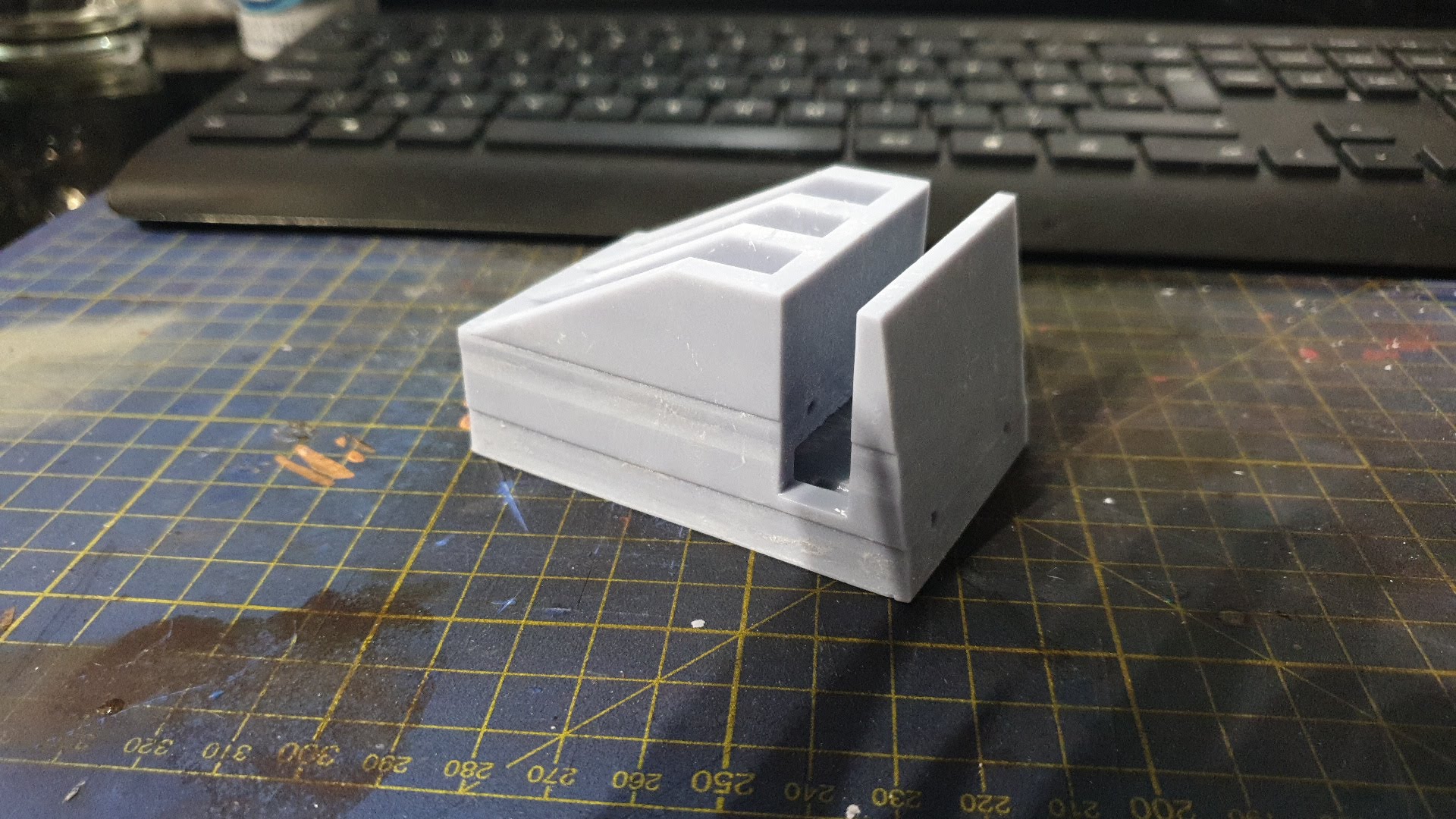
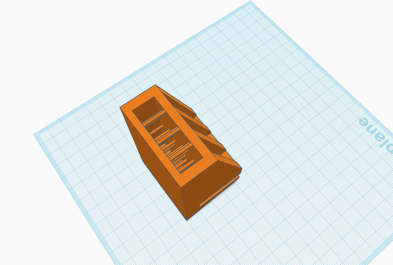 Step 1 - Remove the two channels and instead widen the Arch slot
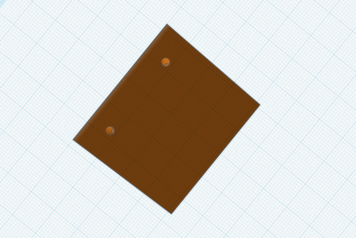 Step 2 - Move the two lower channels (perhaps I should have made these bigger?)
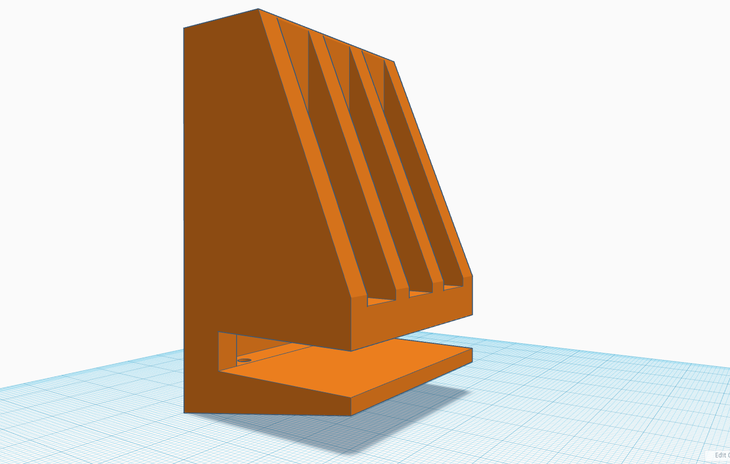 Step 3 - While I'm at it I'm going to tighten the glass table slot as well to see if I can make it a tighter fit.
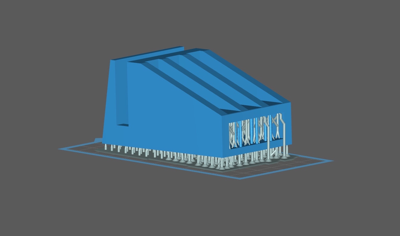
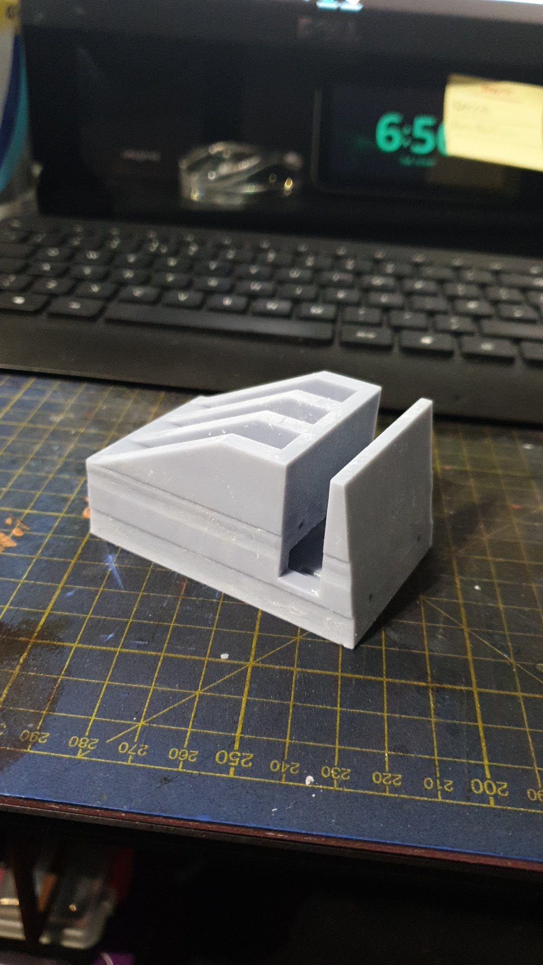
As you can see above, I have adjusted its orientation in chitu box for printing. My thoughts are that there will be less force on the FEP etc printing it at a slight angle and that ‘might’ stop the strange distortion that’s appearing in the prints I have done so far.
And back to the printer once again!

8 Hours…. mmmmm…. That gives me some time to think about how I’m going to switch the damn thing on and off – as there is no power switch!
I’m thinking a smart home solution could be good here…